background image

22

HOW TO CHANGE CONSOLE SETTINGS

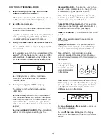
1.   Select the settings mode.

   To select the settings mode, press the Settings 

button. The first settings screen will appear in the 

display. 

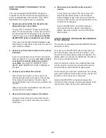
2.   Navigate the settings mode.

   While the settings mode is selected, you can 

navigate through several settings screens. Press 

the Display button repeatedly to select the desired 

settings screen.

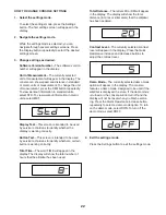
3.   Change settings as desired.


Software Version Number—The software version 

number will appear in the display.


Unit of Measurement—The currently selected 

unit of measurement will appear in the display. The 

console can show speed and distance in standard 

or metric units of measurement. To change the unit 

of measurement, press the St/M button repeatedly. 

To view workout information in standard units, 

select STD. To view workout information in metric 

units, select MET.


Display Test—This screen is intended to be used 

by service technicians to identify whether the 

display is working correctly.


Button Test—This screen is intended to be used 

by service technicians to identify whether a certain 

button is working correctly.


Total Time—The word TIME will appear in the 

display. The display will show the total number of 

hours that the elliptical has been used.

   Total  Distance—The letters MI or KM will appear 

in the display. The display will show the total 

distance (in miles or kilometers) that the elliptical 

has been pedaled.


Contrast Level—The currently selected contrast 

level will appear in the display. Press the Quick 

Resistance increase and decrease buttons to 

adjust the contrast level. 


Demo Mode—The currently selected demo mode 

option will appear in the display. The console 

features a demo mode, designed to be used if the 

elliptical is displayed in a store. If the demo mode 

is turned on, the console will not turn off and the 

display will not be reset when you finish exercis-

ing. Press the Quick Resistance increase button 

repeatedly to select a demo mode option. To turn 

on the demo mode, select DON. To turn off the 

demo mode, select DOFF.

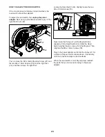
4.   Exit the settings mode.

   Press the Settings button to exit the settings mode.

Summary of Contents for 23937.0

Page 1: ...nual before using this equipment Keep this manual for future reference To register your product and activate your warranty today go to my proform com For service at any time go to proformservice com O...

Page 2: ...S PROFORM and IFIT are registered trademarks of ICON Health Fitness Inc The BLUETOOTH word mark and logos are registered trademarks of Bluetooth SIG Inc and are used under license Google Maps is a tra...

Page 3: ...surface with at least 3 ft 0 9 m of clearance in the front and rear of the elliptical and 2 ft 0 6 m on each side To protect the floor or carpet from damage place a mat under the elliptical 8 Inspect...

Page 4: ...4 UTS STANDARD SERVICE PLANS...

Page 5: ...oyable For your benefit read this manual carefully before you use the elliptical If you have questions after reading this manual please see the front cover of this manual To help us assist you note th...

Page 6: ...w 63 2 PART IDENTIFICATION CHART Use the drawings below to identify the small parts needed for assembly The number in parentheses below each drawing is the key number of the part from the PART LIST ne...

Page 7: ...1 2 If there is a shipping tube not shown attached to the Frame 1 remove the screws not shown and then remove the shipping tube Discard the screws and the shipping tube With the help of a second pers...

Page 8: ...materials not shown under the front of the Frame 1 Tip Make sure to lift the Pedal Arms 16 17 above the Front Stabilizer 3 before you attach it Attach the Front Stabilizer to the Frame 1 with two M10...

Page 9: ...the Rear Upright Cover 25 to the Upright 2 with three M4 x 16mm Screws 78 start all the Screws and then tighten them Then insert the Accessory Tray 24 into the Rear Upright Cover 25 30 31 7 7 Orient...

Page 10: ...ght axle on the Upright 2 Attach the Right Upper Body Arm 10 with an M8 x 18mm Screw 84 and an M8 Washer 83 Repeat this step on the other side of the elliptical 9 9 Identify the Right Rear Arm Cover 2...

Page 11: ...en them Make sure to use the center hole and the two outer holes to attach the Right Pedal Repeat this step on the other side of the elliptical 11 11 Apply a small amount of grease to an M8 x 76mm Sho...

Page 12: ...rews Then tighten all the Screws Repeat this step on the other side of the elliptical 13 13 Have a second person hold the Handlebar 22 in place around the Upright 2 Next locate the Pulse Wires 64 93 i...

Page 13: ...nsole 5 near the Upright 2 plug the Main Wire 89 and the Pulse Wires 64 93 into the receptacles on the Console The connectors on the Main Wire 89 and the Pulse Wires 64 93 should slide easily into the...

Page 14: ...elliptical rocks slightly on your floor during use turn one or both of the leveling feet B beneath the rear stabilizer until the rocking motion is eliminated HOW TO USE THE TABLET HOLDER IMPORTANT Th...

Page 15: ...or the upper body arms H and step onto the pedal I that is in the lowest position Then step onto the other pedal Push the pedals I until they begin to move with a continuous motion Note The pedal dis...

Page 16: ...work outs Each onboard workout automatically changes the resistance of the pedals and prompts you to maintain a target pedaling speed as it guides you through an effective workout You can even listen...

Page 17: ...in the workout Calories per Hour CALS HR The approximate number of calories you are burning per hour Distance MI or KM The distance that you have pedaled in miles or kilometers To change the unit of...

Page 18: ...or Note The console is compatible with BLUETOOTH Smart heart rate monitors Note If you use both heart rate monitors at the same time the BLUETOOTH Smart heart rate monitor will have priority If there...

Page 19: ...you exercise you will be prompted to keep your pedaling speed near the target speed for the current segment When the words TOO SLO appear in the display increase your pedaling speed When the words TO...

Page 20: ...using the Vol increase and decrease buttons on the console or the volume control on your personal audio player THE OPTIONAL CHEST HEART RATE MONITOR Whether your goal is to burn fat or to strengthen...

Page 21: ...the console will turn solid blue 4 Record and track your workout information Follow the instructions in the iFit Smart Cardio Equipment app to record and track your workout information 5 Disconnect yo...

Page 22: ...correctly Button Test This screen is intended to be used by service technicians to identify whether a certain button is working correctly Total Time The word TIME will appear in the display The displ...

Page 23: ...adapter is needed call the telephone number on the cover of this manual IMPORTANT To avoid damaging the console use only a manufacturer supplied regulated power adapter HOW TO ADJUST THE DRIVE BELT I...

Page 24: ...ve the right Disc Locate the Reed Switch 44 Slightly loosen the two M4 x 16mm Screws 78 Next rotate the Pulley 47 until a Magnet 52 is aligned with the Reed Switch 44 Slide the Reed Switch slightly to...

Page 25: ...f and on try to correct the interference by one or more of the following measures Reorient or relocate the receiving antenna Increase the separation between the equipment and the receiver Connect the...

Page 26: ...ic Exercise If your goal is to strengthen your cardiovascular system you must perform aerobic exercise which is activity that requires large amounts of oxygen for prolonged periods of time For aerobic...

Page 27: ...lles Stretch With one leg in front of the other reach forward and place your hands against a wall Keep your back leg straight and your back foot flat on the floor Bend your front leg lean forward and...

Page 28: ...28 NOTES...

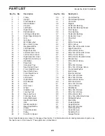
Page 29: ...Crank Arm Spacer 49 2 Crank Bearing 50 1 Crank Bearing Sleeve 51 1 Crank Arm 52 2 Magnet 53 4 Pedal Arm Bearing 54 2 Pedal Arm Bearing Sleeve 55 2 Pivot Spacer 56 4 Pivot Bushing 57 4 Pedal Arm Bushi...

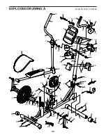
Page 30: ...25 22 24 27 36 38 39 35 35 37 40 41 43 51 46 48 50 52 52 45 42 47 49 48 13 56 59 55 55 60 61 86 68 65 82 62 69 69 70 70 72 72 71 74 74 76 78 78 78 78 78 78 79 79 79 73 75 77 91 92 15 49 80 89 88 88 90...

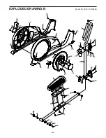
Page 31: ...31 8 10 12 7 11 17 20 21 30 32 29 31 34 38 39 33 54 56 56 58 53 53 57 57 63 66 67 78 78 78 78 78 78 78 78 87 78 81 81 78 78 78 87 14 14 83 84 14 83 EXPLODED DRAWING B Model No 23937 0 R0318A...

Page 32: ...rchased or transported outside the USA 3 if all instructions and warnings in this manual are not followed 4 if the product is abused or improperly or abnormally used or 5 if the product is used for co...

Reviews: