


FP5000 Series User Manual
67
USB Cable Clamp
Section 6.3
USB Cable Clamp
USB Clamp (Type B)
Introduction
When using a USB device, attach a USB cable clamp to the USB interface to prevent the USB
cable from being disconnected.
Attaching USB Clamp (Type B)
NOTE:
Watch your fingers. The edge of the clip is sharp.
DANGER
POTENTIAL FOR EXPLOSION
Verify the power, input, and output (I/O) wiring are in accordance with Class I, Division 2 wiring
methods.
Substitution of any components may impair suitability for Class I, Division 2.
Do not disconnect equipment while the circuit is live or unless the area is known to be free of
ignitable concentrations.
Remove power before attaching or detaching any connectors to or from this product.
Ensure that power, communication, and accessory connections do not place excessive stress
on the ports. Consider the vibration in the environment when making this determination.
Securely attach power, communication, and external accessory cables to the panel or cabinet.
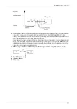
Use either a USB cable by Pro-face or a commercial-type USB cable.
Use only non-incendive USB configurations.
The associated non-incendive field wiring apparatus shall not be connected in parallel unless
approved by the associated non-incendive apparatus.
This product is suitable for use and provides non-incendive field wiring to apparatus in Class
I, Division 2, Groups A, B, C, D.
Failure to follow these instructions will result in death or serious injury.
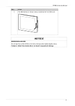
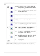
Step
Action
1
Mount the clip to the USB mark
connector shell so that it overlaps. The
clip matches the 32 to 48.5 mm (1.26 to 1.91 in) length of the USB connector.
Summary of Contents for FP5000 Series
Page 1: ...FP5000 Series User Manual FP5000 MM01 EN PDF_02...
Page 6: ...6...
Page 10: ...10...
Page 22: ...Overview 22 KC Markings...
Page 26: ...Device Connectivity 26...
Page 30: ...Parts Identification and Functions 30...
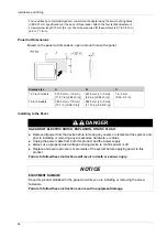
Page 48: ...Dimensions 48 FP 5600TPD External Dimensions 1 Front 2 Left 3 Bottom...
Page 50: ...Dimensions 50 FP 5700TPD External Dimensions 1 Front 2 Left 3 Bottom...
Page 52: ...Dimensions 52...
Page 72: ...Installation and Wiring 72...


