background image

VISTEK V6333E/D & V6333Q/D 
hd/sd sdi digital audio multiplexer


18 


Issue 5 

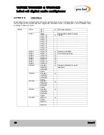
APPENDIX B. 

CONTROLS 

 
These tables show a complete list of all the parameters that can be controlled locally. The tables also show 
the full range of the controls and their ranges and normalised value, if appropriate.  The normalised value 
or setting is shown by the ‘

n

’. 


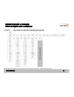
I/P 1 

SDI Input selection 

Video 

I/P 2 


None 


Assign audio inputs to group 

Grp1.1 A 

halves. 

Grp1.1 B 


Grp1.1 C 


Grp1.1 D 


Grp1.1 E 


Grp1.1 F 


Grp1.1 G 


Grp1.1 

Grp1.1 H 


Grp1.2 

Grp1.2 B 

Selection available 

Grp2.1 

Grp2.1 C 

is the same as above. 

Grp2.2 

Grp2.2 D 


Grp3.1 

Grp3.1 E 


Grp3.2 

Grp3.2 F 


Grp4.1 

Grp4.1 G 


Grp4.2 

Grp4.2 H 


Sys Ref 

Assign a reference for each 

AB Ref A 


input pair. 

AB Ref B 


AB Ref 

Async 


Sys Ref 


CD Ref C 


CD Ref D 


CD Ref 

Async 


Sys Ref 


AB Ref E 


AB Ref F 


EF Ref 

Async 


Sys Ref 


CD Ref G 


CD Ref H 


GH Ref 

Async 


Ref Vid 


Async 


Ref IP A 


… 


MAIN 

Sys Ref 

Ref IP H 


Summary of Contents for VISTEK V6333E/D

Page 1: ...l 9 3 1 1 Direct Indications 9 3 1 2 Display and Switches 9 3 2 Remote Control 10 3 3 Menu System 10 3 4 Banner Warnings 11 3 5 Main Menu 11 3 5 1 Video Input Selection 11 3 5 2 Group Selection 11 3 5...

Page 2: ...dio Group Resolution 15 3 7 3 Ancillary Data Blanking 15 3 7 4 Group Deletion 15 3 7 5 Output EDH 16 3 7 6 Display Sleep 16 3 7 7 Display Brightness 16 3 8 Configuration Menu 16 3 8 1 GPI Configuratio...

Page 3: ...ed inputs Single module width The unit automatically detects the standard and format of the SD or HD input video and operates accordingly The unit embeds audio onto SDI video data stream according to...

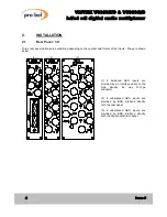
Page 4: ...mber and format of the inputs They are shown below 1 2 3 1 8 balanced AES inputs are provided by an interface cable to the high density 44 way D Type connector 2 4 unbalanced AES inputs are provided b...

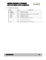
Page 5: ...SDI Video Input 1 HD SDI 2 BNC HD SD SDI Video Input 2 HD SDI LOOP BNC HD SD SDI Re clocked and Buffered Loop through Output HD SDI 1 BNC HD SD SDI Main Output 1 HD SDI 2 BNC HD SD SDI Main Output 2 A...

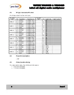
Page 6: ...ES G1 Neg 32 NC 26 GND In AES G1 Gnd 16 NC 11 AES_P4 In AES H2 Pos 1 NC AES H 41 AES_N4 In AES H2 Neg 31 NC 40 GND In AES H2 Gnd 16 NC 9 AES_P5 In AES A1 Pos 23 NC AES A 39 AES_N5 In AES A1 Neg 22 NC...

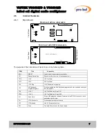
Page 7: ...d to reset the internal microcontroller JP1 Debug Normal Link Should be left with no link for development only TP10 1 5V 1V5 Test Point TP17 3 3V 3V3 Test Point JP4 15V Plug 15V Alternative supply plu...

Page 8: ...right In case of a firmware upgrade one has to make sure that the replaced card sits firmly and straight in the socket with the location peg mating with the positioning hole on the baseboard The Flash...

Page 9: ...where it is When at any level the and buttons will move through the list of options or if in an actual variable such as Video Gain they will change the values If the unit is in Local control then the...

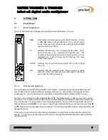
Page 10: ...e for Local or Remote control so always show the operating condition 3 3 Menu System The menus used for local control and status of the module is a hierarchical menu system with five levels as follows...

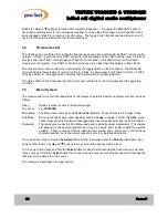
Page 11: ...s The module is a V6333E D and has been inserted into a rear that only has 4 input So inputs E to H can not be used 3 5 Main Menu Here as a guide and a description of the operation of the module are t...

Page 12: ...t in operational installation the V6333 can be used to resample the audio at 48kHz synchronised to various reference signals This may help if the audio is to be de multiplexed at a later stage by anot...

Page 13: ...rrectly configure the module without having to go around the back of the installation to find out what rear the module is plugged into the type of rear is displayed here 4AES BNC 8AES BNC 8AES DTp 3 6...

Page 14: ...r ENG ING MuxGpDel to Grp Del 3 6 10 Audio Reference Displays the selected audio reference as set in the MAIN Sys Ref menu 3 6 11 GPI Status Connecting a GPI input to 0v activates the GPI leaving it o...

Page 15: ...io onto SD to 20 bits Grp1 24b Let the embedding of audio onto SD be 24 bits Grp2 Res Control for Group 2 s audio resolution Etc 3 7 3 Ancillary Data Blanking If the SDI into the V6333 has audio alrea...

Page 16: ...nt panel will not be visible so it will go to sleep after a certain time This timeout delay can be changed on the ENG ING Sleep menu to be anything between 0 and 30 minutes 0 minutes means that it wil...

Page 17: ...En Grp2 2 Option Grp2 2 Vid Src En Grp3 1 GPI 1 Grp3 1 I P Std En Grp3 2 GPI 2 Grp3 2 I P 1 En Grp4 1 GPI 3 Grp4 1 I P 2 En Grp4 2 GPI 4 Grp4 2 AES ABCD Grp1 Res PCB Rev AB Ref AES EFGH Grp2 Res H W...

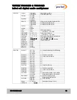
Page 18: ...ction Video I P 2 None Assign audio inputs to group Grp1 1 A n halves Grp1 1 B Grp1 1 C Grp1 1 D Grp1 1 E Grp1 1 F Grp1 1 G Grp1 1 Grp1 1 H Grp1 2 Grp1 2 B n Selection available Grp2 1 Grp2 1 C n is t...

Page 19: ...States Active Inactive Soft Ver 00 00 00 Version numbers FPGA Ver 00 00 MCPLDVer 00 00 DCPLDVer 00 00 PBC Ver 00 00 STATUS Boot Ver 00 00 00 G1 1 On n Group Embedding On Off Muting G1 1 Off EnGrp1 1...

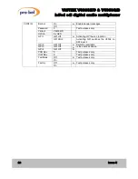
Page 20: ...33E D Option 8 x AES GPI Off n Activating GPI has no function GPI 1 GPI SDI2 Activating GPI switches the V6334 to SDI input 2 GPI 2 GPI Off n Selection available GPI 3 GPI Off n is the same as above G...

Page 21: ...ix Definition SMPTE Colloquial 1920x1080 60 2 1 274M 4 1080i60 1920x1080 59 94 2 1 274M 5 1080i59 1920x1080 50 2 1 274M 6 1080i50 1920x1080 30 1 1 274M 7 1080p30 1920x1080 29 97 1 1 274M 8 1080p29 192...

Reviews: