background image

4. Inspection of the cutoff saw before use: 

. Make sure there are no loose objects on or near the saw. 

. Except for the carburetor adjustment screws, all other bolts, nuts, screws and the 

fuel tank cap should be securely tightened. Make sure all rubber hoses for oil flow 
are tightly connected with no leaks. 

. Make sure the blade rotates smoothly; the starter rope can be pulled through and 

guided back without being tangled. 

. Check to make sure the Throttle Trigger, the Full Throttle Lock Button, the Choke 

Lever, the Decompression Valve and the kill Switch all function well without failure. 


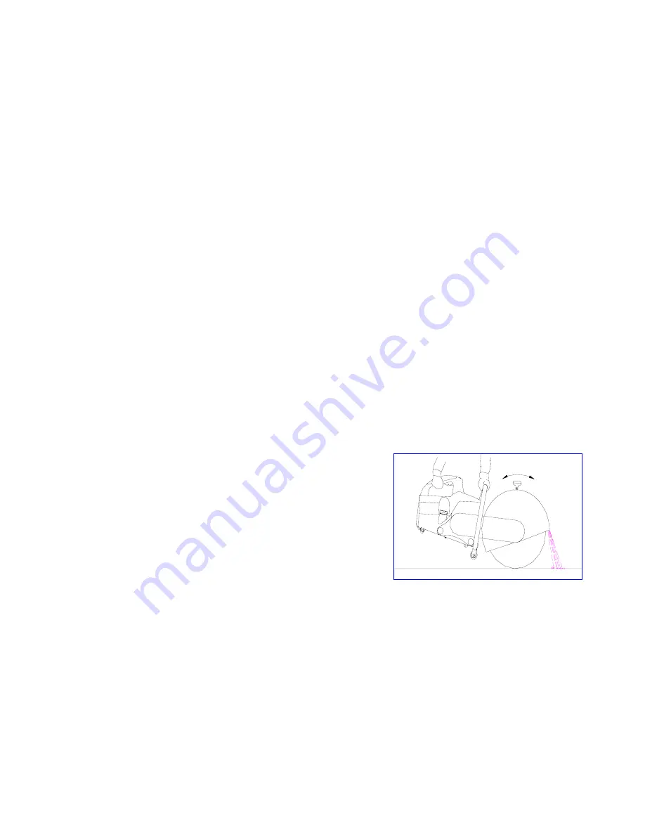
. Check to make sure the blade guard has no 

visual damage. Adjust the guard as necessary 
so the spark beam generated during cutting 
can be directed away from the operator. (Ref. 
Fig.2) 


Fig 2 

16 

Summary of Contents for EHS350A

Page 1: ...Portable Cut off Saw Model EHS350A Operation Parts Manual WARNING For safety and efficient operation always follow the instructions in this manual...

Page 2: ...Model EHS350A cut off saw To receive maximum performance and satisfaction from your cut off saw model EHS350A it is important that you read and understand the maintenance and safety manual before ope...

Page 3: ...Because the EHS350A operates at high speed special safety precautions must be observed before operating the saw Careless or improper use could cause serious or even fatal injury 1 2...

Page 4: ...ications 21 22 Operation guide to EHS350A cut off saw 23 32 1 Before starting 23 26 2 Starting 27 29 3 Operation 30 4 Emergency Stopping 31 5 Notes on operation 31 32 Adjustment of EHS350A cut off saw...

Page 5: ...ing pawl 39 5 Maintenance chart 40 41 Storing EHS350A cut off saw 42 Exploded parts views and parts lists 43 58 1 Crankshaft Housing Assembly 43 44 2 Crankshaft Piston Assembly 45 46 3 Cylinder Muffle...

Page 6: ...ngine and a driving cutting system When engine speed is up to 3800 RPM the cutting blade driven by the engine via belt transmission system begins to rotate at high speed and is ready for cutting work...

Page 7: ...7 Kill Switch 8 Full Throttle Lock Button 9 Throttle Trigger 10 Rear Handle 11 Filter Cover Lock Lever 12 Air Filter 13 Choke Lever 14 Starter Grip 15 Fuel Tank Cap 16 Decompression Valve 17 Water At...

Page 8: ...the operating speed of the blade should be above or equal to 5300 RPM 2 Flanges Clamp and support the diamond or abrasive blade 3 Hexagon Bolt Tightens blade flange 4 Blade Guard Safety guard directs...

Page 9: ...ens the throttle and the engine accelerates Releasing the trigger slows down the engine 10 Rear Handle Used to securely hold the saw while under operation 11 Filter Cover Lock lever Locks the air filt...

Page 10: ...e it automatically closes 17 Water Attachment Feeds water to both sides of diamond blade Connect to water supply for wet cutting 18 Tensioning Nut For V belt tension adjustment Turn this nut clockwise...

Page 11: ...s before operating this cut off saw 1 Worksite Requirements The worksite should be free of any materials or objects that are flammable or explosive Surroundings should be in order with no clutters hav...

Page 12: ...blade is above or equal to the spindle speed of your cut off saw Inspect the cutting blade frequently and replace immediately if the cutting blade is cracked or warped Cracked or warped blades may sh...

Page 13: ...imbedded in their cutting edges Wet or dry cutting is possible Cutting wet will extend the life of your diamond blades A water attachment comes as standard equipment with the EHS350A Before using the...

Page 14: ...e sure you are in good physical condition and are not under the influence of any substance such as drugs or alcohol which may impair vision or dexterity Take breaks as needed to prevent you from getti...

Page 15: ...to protect your legs Do not wear shorts Protect your hands with gloves when handing the cut off saw Heavy duty non slip gloves improve your grip and protect your hands Use EHS350A cut off saw only wit...

Page 16: ...erate dust mists and fumes containing chemicals known to cause serious or fatal injury or illness such as respiratory disease cancer birth defects or other reproductive harm Cutting masonry concrete a...

Page 17: ...d with no leaks Make sure the blade rotates smoothly the starter rope can be pulled through and guided back without being tangled Check to make sure the Throttle Trigger the Full Throttle Lock Button...

Page 18: ...embled and properly adjusted 5 Precautions on starting Keep a good balance and secure footing Take hold of the starter grip firmly do not wrap the rope around your hand To start place the machine firm...

Page 19: ...object Make sure the cutting depth is appropriate Do not change direction of the cut or twist during the cut as this may produce a high torsion load on the blade and may cause it to break or shatter...

Page 20: ...s running Take precaution when re entering a cut and do not turn the blade at an angle or push it into the cut as this may result in a pinching of the blade 7 Precautions on fueling Fuel the machine o...

Page 21: ...ny hard objects Notes on maintenance Perform any maintenance or repair work in clean and neat environment Use proper tools and operate with caution 9 Do not attempt to modify your cut off saw in any w...

Page 22: ...r bore 49mm Piston stroke 34mm Displacement 64 1 cc Max output 2 70 kw 3 8 hp Speed at max output 8500 rpm Max torque 3 5N m Idle speed 2400 rpm Lock up speed of clutch 3800 rpm Min fuel consumption 5...

Page 23: ...through the rope starter Engine Rotation direction Clockwise Diameter Maximum 355 mm 14 Max operating speed 5300 rpm Thickness 2 6 6 mm 0 1 0 24 Arbor hole diameter 20 mm Types Composite abrasive bla...

Page 24: ...Before starting check if there is any fuel left in the fuel tank b This engine is engineered to operate on mixture of unleaded gasoline and quality two stroke engine oil Octane rating of the gasoline...

Page 25: ...0 mm 1 Blade thickness should be within the range of 2 6 6 mm 100 240 b Blade types For your reference choose composite abrasive blades for cutting of asphalt concrete stone brick steel and plastics C...

Page 26: ...res on the belt pulley 3 Use the combination wrench to loosen and unscrew the hexagon bolt 4 Remove the metal washer 5 the flange 6 from the arbor together with the blade to be replaced Mount the new...

Page 27: ...belt guard 1 and then remove the V belt guard Loosen the three hexagon bolts 4 on the bearing plate 3 Turn the tensioning nut 5 clockwise until the V belt is tensioned Tighten the three hexagon bolts...

Page 28: ...Press the button of the decompression valve 1 Set the choke lever 2 to an appropriate position to if the engine is cold to if the engine is warm even if the engine has already run but is still cold F...

Page 29: ...ength otherwise it may break or cause damage to the starting system b Do not let go of the starter grip c After pulling guide the rope back into place slowly d Pull the rope only straight up and down...

Page 30: ...ttle lock button 4 reverts to its original position and the engine idles If the engine is new or has been stored for a long period of time pull the starter rope through several times to ensure that su...

Page 31: ...oward the object to be cut After the cutting edge comes in contact with the object increase pressure to the saw slowly until the blade is at the desired depth Finally hold the machine securely and mov...

Page 32: ...te that the service life of some components of the saw may be adversely affected if the engine is stopped too often during cutting Fig 8 5 Notes on operation Follow all applicable instructions in this...

Page 33: ...sioning the V belt 2 Adjusting carburetor The carburetor has been preset and adjusted at the factory to reach the optimum fuel air mixture for a smooth fuel efficient reliable running engine with low...

Page 34: ...idle speed after Standard setting adjustment a To adjust idle speed start the engine first If the idle speed is too low the engine may shut off after starting In this case make the standard setting fi...

Page 35: ...LA counter clockwise until the blade stops running Then turn the screw LA 90 further counter clockwise 3 Adjusting blade guard Ref Fig 10 The blade guard deflects sparks from the operator Move the adj...

Page 36: ...ting jobs as well as material being cut both wet or dry For dry cutting maintenance is required every 48 hours For instructions see below Ref Fig 11 Set the choke lever to Pull the filter cover lock l...

Page 37: ...results in trouble in en Therefore if the engine is down on power difficult to start or runs poorly at idling speed first check the spark plug e carbon deposits tion gine opera Remove the spark plug c...

Page 38: ...he engine unit Remove the spring clip 8 remove the rope rotor 7 with pawl 9 Using a screwdriver unscrew the screw plug 3 on top of the starter grip remove the starter rope 4 out of the grip Put a new...

Page 39: ...ng clip must point counter clockwise To tension the rewind spring first guide the rope through the notch on the edge of the rope rotor and form a loop use it to turn the rope rotor 4 5 times counter c...

Page 40: ...nscrew the screws 2 on the flywheel starter cover 1 and remove the cover from the engine unit Remove the spring clip 8 Remove the damaged pawl 9 Replace a new pawl Refit the spring clip 8 and the flyw...

Page 41: ...orking hours Before starting work After work or daily Every time after refueling Weekly Monthly In the event of a malfunction If damaged As required Visual inspection Complete Machine Clean Throttle t...

Page 42: ...eplace Check idle speed the cutting wheel must not run Carburetor Adjust idle speed Spark plug Adjust electrode gap Nuts and bolts but not adjusting screws Retighten Rubber buffer Replace Check and cl...

Page 43: ...t and storage 1 Avoid knocks and bumps 2 Abrasive blades must not be exposed to direct sunlight or other sources of heat during transport and storage 3 Store the machine in a place free of moisture an...

Page 44: ...1 Crankshaft Housing Assembly Item Ref Description Qty 1 1E49F01011 Screw M5 20 10 43...

Page 45: ...seal 17 28 7 1 8 1E49F01001 Crankshaft housing Left 1 9 GB T276 94 Ball bearing 6203 1 10 1E49F01003 Gasket 1 11 1E49F01004 Positioning Sleeve 2 12 1E49F01002 Crankshaft housing Right 1 13 B455 Oil s...

Page 46: ...2 Crankshaft Piston Assembly 45...

Page 47: ...005 Spring Cover 1 21 1E49F02007 05 Retainer 3 7 1E49F03004A Rope rotor 1 22 1E49F02007 06 Clutch 1 8 1E49F03009A Pawl 1 23 1E49F02007 04 Tension spring 3 9 1E49F03008 Spring clip 1 24 1E49F02007 02 R...

Page 48: ...3 Cylinder Muffler Assembly 47...

Page 49: ...E49F04004 Cylinder cover 1 4 1E49F07016 Screw M5 16 3 5 1E49F01011 Screw M5 20 4 6 1E49F04002 03 Washer 1 7 1E49F04002A Decompression valve 1 8 1E49F04005 Exhaust gasket 1 9 1E49F08000A Muffler Assemb...

Page 50: ...4 Fuel Tank Carburetor 49...

Page 51: ...Tank Cap 1 5 1E49FA06005 Choke lever 1 17 1E49F07015 Washer 1 6 1E49F06003 Air hose 1 18 1E49F07014 Tank vent 1 7 1E49F06001 Carburetor 1 19 1E49FA07003 Gasket 1 8 1E49F07020 Screw M5 65 2 20 1E49F070...

Page 52: ...5 Handle Main Cover Assembly 51...

Page 53: ...49FA5001 Kill switch 1 6 GB T845 85 Screw ST2 9 13 2 7 1E49FA09010 Handle molding 1 8 1E49F09010 03 Torsion spring 1 9 1E49F09010 02 Full throttle lock button 1 10 1E49FA09003 Throttle trigger 1 11 1E...

Page 54: ...6 Air Filter Assembly 53...

Page 55: ...006 Paper Air Filter 1 6 1E49F10007A Secondary filter 1 7 GB T845 85 Screw ST2 9 19 2 8 1E49FA10003 Half round 1 9 1E49FA10002 Filter base 1 10 1E49F06007 Gasket 1 11 1E49F07016 Screw M5 16 2 12 1E49F...

Page 56: ...7 Cutter Assembly 55...

Page 57: ...1 21 EHS400 01004A Support 1 7 EHS400 01006A Blade Guard 400mm 1 22 EHS400 01021A Ring 1 8 EHS400 01007A Handle 1 23 GB T276 94 Ball bearing 6202 2 9 EHS400 01026 Screw M6 16 2 24 EHS400 01008 Belt P...

Page 58: ...8 Transmission Box Assembly 57...

Page 59: ...7018 screw M5 25 2 5 1E49F01011 Screw M5 20 5 16 GB894 1 86 Spring lock 8 2 6 EHS400 02005A Clamping lever 1 17 1E49F07021 Screw M5 24 2 7 EHS400 02006A Cover 1 18 EHS400 03001 A Handle frame 1 8 1E49...

Reviews: