background image

128-9300

 6 of 24

6

IMPORTANT!

DO NOT PLUG THE EIGHT PIN MAIN POWER HARNESS OR THE MULTI PIN INPUT/OUTPUT HARNESS 

INTO THE CONTROL MODULE UNTIL ALL CONNECTIONS TO THE VEHICLE HAVE BEEN MADE.  AFTER 

SELECTING YOUR TARGET WIRES AS DEFINED BELOW, DISCONNECT THE NEGATIVE BATTERY 

CABLE FROM THE VEHICLE BATTERY PRIOR TO MAKING ANY CONNECTIONS.

NOTE:


Do not remove the fuse holders from this wire harness.  Fuses must be used and located 

as close as possible to the power source for adequate protection of the vehicle.

 WIRING THE 6 PIN MAIN POWER HARNESS:  


PART # 1123742

NOTE:


Do not remove the fuse holders from this wire harness.  Fuses must be 

used and located as close as possible to the power source for adequate protection 

of the vehicle.

1 BLUE Wire: 

 Ignition 1 Output

Connect this wire to the ignition 1 wire from the ignition switch.  This wire will show +12 volts when the  

ignition key is turned to the "ON" or "RUN" and the "START" or CRANK" positions and will have 0 volts when 

the key is turned to the "OFF" and "ACCESSORY" positions. 

For Diesel Applications, this wire must be connected to the ignition circuit that powers the glow plugs if the 

vehicle requires glow plug pre-heating. (See selectable feature Bank 3 #12)

2 RED/WHITE WIRE:

  + 12 volt Battery 1 Source Fused 30A

Locate the vehicle battery wire(s) at the ignition switch.  Verification: These wires will register voltage in all positions of 

the ignition switch.  Connect the Red w/White wire to the vehicle's battery wire.  This wire provides power for the control 

circuit as well as the ignition 1 and ignition 2 relays.

3 GREEN Wire:  

Ignition 2 Output

Connect this wire to the ignition 2 wire from the ignition switch.  This wire will show + 12 volts when the 

ignition key is turned to the "ON" or "RUN" position and is some cases the "START" or CRANK" position.  

This wire will show  0 volts when the key is turned to the "OFF" and "ACCESSORY" positions.

NOTE: 

See programming information (Bank 3 Selection #7) concerning this wire to allow output during the 

"START" mode. 

4 PURPLE Wire:

 Accessory Output

Connect this wire to the Accessory wire from the ignition switch. This wire will show + 12 volts when the 

ignition switch is turned to the "ACCESSORY" or "ON" and "RUN" positions, and will show 0 volts when the 

key is turned to the "OFF" and "START" or "CRANK" positions.

5 RED WIRE: 

 + 12 Volt Battery 2 Source Fused 30A

Locate the vehicle battery wire(s) at the ignition switch.  Verification: These wires will register voltage in all positions 

of the ignition switch.  Connect the Red  wire to the vehicle's battery wire.  This wire provides power for the start relay 

and the accessory relay.

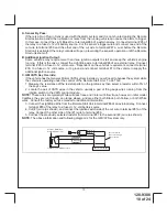
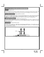
6 YELLOW Wire: 

 Starter Output

Careful consideration for the connection of this wire must be made to prevent the vehicle from 

starting while in gear.  Understanding the difference between a mechanical and an electrical  

Neutral Start Switch will allow you to properly identify the circuit and select the correct installation 

method.  In addition you will realize  why  the connection of  the safety wire is required for all me-

chanical switch configurations.  

Failure to make this connection properly can result in personal injury and property damage.

In all installations it is the responsibility of the installing technician to test the remote start unit and  ensure 

that the vehicle cannot start via RF control in any gear selection other than park or neutral.

Summary of Contents for APS-901E

Page 1: ...age 12 13 Telematic Port Information Page 13 6 Pin Antenna Harness Page 13 Diesel Engine Settings Page 14 DBI Port Information Page 14 Engine Monitoring Selections Voltage Tach DBI Hybrid Page 14 Tach...

Page 2: ...air bags or damage sensitive vehicle computers and electronics For technical support go to www avxtech1 com or call 1 800 225 6074 FCC COMPLIANCE This device complies with Part 15 of the FCC rules an...

Page 3: ...bit Shutdown To Brake Switch 5 Brown Inhibit Shutdown To Brake Switch 6 Gray Inhibit Neutral Start Switch 7 Black Yellow Pulse During Crank Output 8 Black Red Pulse After Shut Down Output 9 Black Blue...

Page 4: ...ed White Battery 1 12V 3 Green Ignition 2 4 Purple Accessory 5 Red Battery 2 12V 6 Yellow Starter Output 1 Black Chassis Ground 2 White Red Parking Light Relay Input 3 Yellow Black To Controlling Alar...

Page 5: ...as it is not waterproof HOOD PIN SWITCH PART 1363699 The pin switch included in this package is intended for protecting the hood area of the vehicle In all cases the switch must be mounted to a ground...

Page 6: ...nition 2 Output Connect this wire to the ignition 2 wire from the ignition switch This wire will show 12 volts when the ignition key is turned to the ON or RUN position and is some cases the START or...

Page 7: ...gative side of the ignition coil This Remote Start unit learns the tach rate of the vehicle and in most cases will operate properly from one coil pack regardless of the number of cylinders If the unit...

Page 8: ...hen the vehicle is in any gear other than Park or Neutral this wire can be connected to that vehicle wire to prevent starting while in gear If the vehicle you are working switches ground to the brake...

Page 9: ...rs if the doors unlock automatically when the factory anti theft system is disarmed This wire will also activate when the transmitter is used to arm lock the system This output can be selected to oper...

Page 10: ...irement connect terminal 30 to a fused 12 volt source or to ground and connect terminal 87 to the vehicle to supply the additional ignition source C GM VATS Key Override If the vehicle has the General...

Page 11: ...sher relay If the vehicle you are working on has 12 volt switched parking lights connect this wire to a fused 12 volt source Max 15 Amps NOTE If the vehicle s parking lights are ground switched connec...

Page 12: ...vides a ground pulse when the transmitter button is pressed and held for 3 seconds while running under control of the remote start Connect the Green wire to the low current ground signal wire from the...

Page 13: ...White Data TX Yellow Data RX Connect the 4 pin harness found in the Telematic one way or Carlink II kits to the mating port on the con trolling circuit NOTE If using the TWO WAY Telematic module only...

Page 14: ...el to go above the level it was before the vehicle began to crank which indicates the vehicle is running Feature 14 of Bank 3 must be set for averaging or the voltage sense feature will not operate in...

Page 15: ...The intent of the hood pin safety shut down is to prevent the Remote Start unit from being activated while a mechanic or vehicle owner is performing normal routine vehicle maintenance To test the inte...

Page 16: ...ear selector to the drive position If the unit attempts to start failing this test recheck your Yellow Wire s connection This wire must be connected to the ignition switch side of the Neutral Start Sw...

Page 17: ...r than Park or Neutral while the key is in the ignition cylinder however if the key is left in the ignition switch and the door is left opened the added relay will be energized causing a 150mA drain o...

Page 18: ...Striped side must be connected to the hood pin switch If the hood pin switch is also used for an alarm trigger input be certain to use the dual diode set up shown earlier in this manual AFTER THE CONN...

Page 19: ...e to feature 2 etc then use the lock button of the transmitter to select the feature setting Example to set passive arming 1 Turn the ignition key to the on position 2 Press and release the valet prog...

Page 20: ...ee Transmitter Programming Guide RF Programmable Features Bank 2 Is Alarm Selectable Features Feature Selection 1 Chirp 2 Chirps 3 Chirps 4 Chirps 5 Chirps 6 Chirps 1st DoorL UL 500 mS 3 5 Sec 500mS L...

Page 21: ...s 5 Press the push button switch five times to advance to features 5 Input Check then use the lock button of the transmitter to select three chirps DBI Tach 6 To exit the programming mode turn the ign...

Page 22: ...l 20 13th Temp Start Not Available 14th Crank Averaging Averaging Preset Time NOTE When averaging the engine must be started 4 times with the key to be effective 15th R S Shock Not Available 16th Turb...

Page 23: ...128 9300 23 of 24 23 NOTES...

Page 24: ...k Yellow Pulse During Crank Output Black Blue Pulse Before Start Output Black LT Green Pulse After Start Output Gray Black Inhibit Shut Down From Hood Switch Brown Black Inhibit Shut Down From Brake S...

Reviews: