128-9300
11 of 24
11
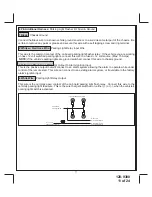
Typical Vehicle Parking Lights
From Vehicle
Park Light Switch
White From
Remote Start Module
To + 12 Volts
(If Gnd. Switch See Note)
White/Red Wire From
Remote Start Module
15A
4 Pin Additional Harness:
Parking Light Flasher I/O Siren & Ground
1 Black:
Chassis Ground
Connect the Black wire to a known vehicle ground source or to a solid clean metal part of the chassis. Be
certain to remove any paint or grease and secure this wire with a self tapping screw and ring terminal.
2 White w/ Red trace Wire:
Parking Light Relay Input Wire
This wire is the common contact of the on board parking light flasher relay. If the vehicle you are working
on has +12 volt switched parking lights, connect this wire to a fused + 12 volt source. (Max. 15 Amps)
NOTE:
If the vehicle's parking lights are ground switched, connect this wire to chassis ground.
3 Yellow w/ Black trace Wire:
(+)
Output To Alarm Ignition Input
This is the positive output that will connect to an alarm system allowing the alarm to operate while under
control of the remote start. This wire can connect to an existing alarm system, or if available to the factory
alarm's ignition input.
4 White Wire:
Parking Light Relay Output
This wire is the normally open contact of the on board parking light flash relay. Connect this wire to the
vehicle's parking light feed wire. This is the wire that gets switched on, either (+) or (-), when the vehicle's
parking light switch is activated.
Summary of Contents for APS-901E
Page 23: ...128 9300 23 of 24 23 NOTES...


