PREMIER TECH Solido SMART Operating Manual Including Operations Logbook, Manual For Installation, Commissioning And Maintenanc Download Page 38

7. Installation and start-up 


Premier Tech 

38 / 64 

Solido SMART 


DOKK5110E    15.04.2020


7.3.6 

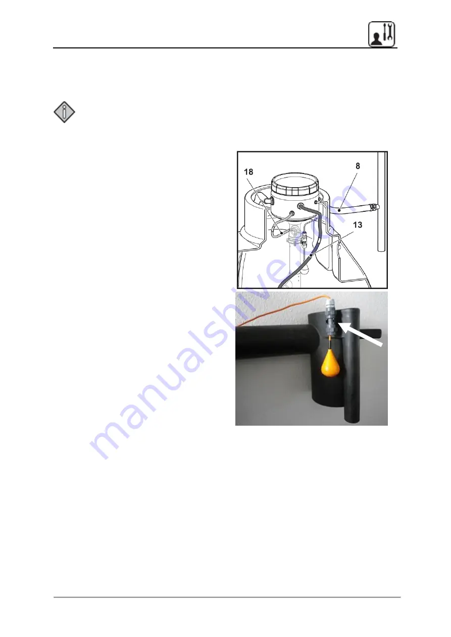
Connecting the technology capsule 


Remove the supply air hose (

8

), the blue compressed air hose (

18

) that is pre-assembled 

in the container, and the white tube diffuser hose (

13

). 


If necessary, shorten the compressed air hoses to the required lengths. 


Note: 

The length of the hoses is sufficient for installation with a shaft design of max. 
1.20 m. With the standard version as per the scope of delivery, shortening the 
hoses by up to 60 cm is recommended). 


Connect the hoses according to the 
colour coding. 


Connect the supply air house to the 
capsule outside the shaft. 


Loosely bundle the hoses using a cable 
tie, and place them around the capsule. 


Lock the SWS float switch in place on 
the pre-assembled retaining clip for the 
sampling bottle in the container. 


Fix overfill alarm (float switch SWS) to 
the pre-installed clip at the sample pot 


Please check that the clip clicks between 
the two sleeves (see white flash). 


7.3.7 

Inserting the technology capsule 


Slightly turn the capsule when lowering it onto the shaft, so that the hoses are placed 
around the capsule. 


Carefully place the technology capsule onto the holder on the top end of the clearwater 
lifter so that the capsule is positioned securely. For larger installation depths, the capsule 
can be positioned on an extension pipe (HT DN75, 1 m long, purchase order number 
KKZT0033) to improve accessibility. 


Make sure that all hoses are connected properly so that they lie next to the capsule in the 
shaft and ensure that it is possible to remove the capsule for maintenance purposes. 


7.3.8 

Notes for plants with pumped outlet KWP (option) 

Please note information for plants with pumped outlet in separate manual DOKK7314E, 
which is included in the delivery and part of warranty conditions.


Summary of Contents for Solido SMART

Page 1: ...cluding Operations Logbook Manual for Installation Commissioning and Maintenance Fully Biological SBR Small Wastewater Treatment Plant without primary treatment Qualified advice by telephone 49 0 30 4...

Page 2: ...to do so is permitted only if the power has been switched off and the applicable accident prevention regulations are observed oxygen deficiency Observe the safety instructions in the relevant chapters...

Page 3: ...o a factory warranty of 3 years The factory warranty of 3 years for the Solido SMART treatment system covers the service life of all of the electrical and mechanical components provided that start up...

Page 4: ...foundation 20 cm from filling material 2 Verify the integrity of the containers and their components and carefully place them into the pit without damaging them 3 Fill up lifter with water due to upl...

Page 5: ...t DN 50 DN100 Install the sealing to the building in such a way that it is possible to change the cable at a later point 3 Connect the hoses Attach the pre fitted hose on the lifter and the supply air...

Page 6: ...maintenance 22 6 Inspection maintenance and desludging 23 6 1 Opening and closing the TopCover 23 6 2 Monthly in house inspection 24 6 3 Half yearly maintenance 25 6 4 Take sample of activated sludge...

Page 7: ...8 8 Alarm relay for an external signaller 50 8 9 Service and maintenance specialist companies only 50 9 Operational failures and resolving them 51 9 1 S40 control alarm messages 51 9 2 Other failures...

Page 8: ...KK5204 Installation manual for Solido SMART pumped outlet DOKK7314E Installation instructions for kiosk DOKK7301 Solido SMART is used in the container types round tank BL and rectangular tank M2 also...

Page 9: ...n and maintenance personnel The chapters that the operator must read and with instructions based upon which the operator must act are indicated with the operator symbol Descriptions that the operator...

Page 10: ...do SMART SBR wastewater treatment system is used to clean and purify wastewater in domestic areas This wastewater treatment system is not intended for any other use Any other improper use may cause da...

Page 11: ...bility of the specialist company and must be agreed upon with the manufacturer Never enter the system unless the power has been switched off and the applicable accident prevention regulations are bein...

Page 12: ...ance purposes Caution Comply with the relevant accident prevention regulations at all times There should always be two people present when a wastewater treatment plant is entered Never enter after a p...

Page 13: ...erview 1 BL26 container example 2 Solido SMART technology capsule with compressor and solenoid valves 3 Tube diffuser BEL 4 Air hose 5 Lower part of the inlet and sludge pipe 6 Supply air hose and sup...

Page 14: ...DN160 Air inlet support Technology capsule Sampling pot with overflow protection Tube diffuser 1 Tube diffuser 2 Clearwater lifter Baffle Characteristics chambers are connected by openings in baffle b...

Page 15: ...tor It is available in a variety of versions for different numbers of users referred to in the text below as inhabitants The special feature of the plant design is that all mechanical coarse material...

Page 16: ...etween the activated sludge and clearwater is performed in a sedimentation phase lasting 90 minutes at minimum followed by the discharge of clearwater The clearwater is extracted using compressed air...

Page 17: ...er 8 S40 control unit and available settings Holiday economy mode For longer periods where no wastewater is generated e g holidays you can select an economy mode for max 120 days In this case the aera...

Page 18: ...g a pictograph and that ensures proper desludging Desludging is required if the sludge level reaches 70 of the max permitted water level at the end of the sedimentation You must check whether the func...

Page 19: ...pecialist maintenance service Ensure longer permeability in the downstream filtration systems and therefore a longer service life for your plant 5 1 Everyday conduct Please observe the codes of conduc...

Page 20: ...nitary towels tampons Dustbin Textiles cleaning cloths etc Dustbin Wallpaper adhesive Collecting point Overloading the small wastewater treatment plant through Proper disposal Ash Dustbin Cooking oil...

Page 21: ...exceed the limit values stipulated by the authorities even if the plant is in perfect technical and biological working order Running in phase and purification efficiency The full biological purificati...

Page 22: ...ouse inspection 5 5 Half yearly maintenance as per German law In accordance with the legal water usage permit the operator must take out a maintenance contract with a specialist company qualified expe...

Page 23: ...y after completing the work on the wastewater treatment plant by turning the locking latch on the TopCover to the locked position for example as a child safety feature Opening the cover Turn both of t...

Page 24: ...d discharge for blockages visual inspection Check the plant for any floating sludge Enter the operating hours of the aggregates into the operations logbook also see chapter 5 7 Important documents for...

Page 25: ...the operation parameters on the basis of inspection results from the SBR and outflow if necessary in consultation with Premier Tech Warning Disconnect the wastewater treatment plant from the power su...

Page 26: ...he integrated sampling container in the outflow immersion pipe The maintenance activities specified above are performed and the inspection results are recorded in a maintenance report This maintenance...

Page 27: ...arwater from sample pot using the small sample taking device to reach 1 3 dilution allow settlement for 30min multiply resulting sludge level by factor 4 to get SSV30 in ml l take picture and save it...

Page 28: ...f SSV30 to SSV90 30 resp 90 min sedimentation SSV30 measurement of sludge level in reactor in 1 3 dilution after 30min sedimentation at current water level HR during service HR current water level at...

Page 29: ...30 5 PE 1 12 m 1 96 EBL 45 8 PE 1 35 m 2 24 EBL 52 10 PE 1 54 m 2 21 EBL 76 15 PE 1 68 m 2 28 EBL 99 20 PE 1 81 m 2 28 EBL 76X2 30 PE 1 71 m 2 28 EBL 99X2 40 PE 1 81 m 2 28 EBL 99X3 50 PE 1 85 m 2 28...

Page 30: ...d of the system or take out the capsule for desludging The design of the pipe will make sure that at least 10 of the volume will stay inside the tank This is mandatory to keep up the performance of th...

Page 31: ...ox for plants with lifter Item Quantity Description 1 1 pc Technology capsule 2 1 pc Control cable grey with connection plug 15 m or 30 m pre assembled 3 1 pc Compressed air outlet for tube diffuser B...

Page 32: ...11 1 pc Shaft assembly set 12 1 pc Air vent for air inlet support 13 1 pc tube diffuser with hose DN13 and or DN16 tank M2 additional tube diffuser T piece stop cock 1 pc Optional without a figure DN...

Page 33: ...t system are already pre installed see figures Pre installed components in the treatment tank BL Item Quantity Description 14 1 pc Shaft 15 1 pc Cover 16 1 pc Technology capsule holder 17 1 pc Lower p...

Page 34: ...art up Premier Tech 34 64 Solido SMART DOKK5110E 15 04 2020 Pre installed components in the treatment tank M2 Sludge removal pipe DN160 clearwater lifter Sampling pot with emergency overflow Support f...

Page 35: ...ly air hose and cable conduit set in place Is the cable holder installed 6 Is the air inlet support set in place Is the hose pulled into the shaft up to the red marking Standard hose length 3 m extens...

Page 36: ...u must fill the lifter with water using a hose before you fill the container Note There is a risk of rapid uplift when the lifter is completely empty 7 3 3 Assembling the tube diffuser Place the tube...

Page 37: ...that can comfortably be guided up to the top ground surface remains in the shaft Set the aeration cap included in the scope of delivery onto the air inlet support 7 3 5 Laying the control cable Place...

Page 38: ...ling bottle in the container Fix overfill alarm float switch SWS to the pre installed clip at the sample pot Please check that the clip clicks between the two sleeves see white flash 7 3 7 Inserting t...

Page 39: ...ectrical socket for connecting the Solido SMART technology capsule standard design A mains cable for connecting to the mains supply A type plate see details in chapter 10 Symbols on the control unit C...

Page 40: ...reased to 125 of the set value The duration of the start up phase can be set The start up phase can be activated optionally 8 2 Navigation in the control menu You can use the three arrow buttons on th...

Page 41: ...lish The following parameters are requested in the following order using a comparable logic Language Set time Password 7682 fixed only valid for start up or service password based on the established p...

Page 42: ...trol unit has a power failure recognition function If the power supply is interrupted a recurring audible alarm is emitted Network not available is displayed on the screen Switch off the alarm complet...

Page 43: ...h to a weekly display Changes can be made to the system settings for example changes to the alarm pause time interval in which no audible alarm is emitted Settings and a test mode that must be made an...

Page 44: ...to 50 of the set value You can ignore lines 5 and 6 BEL and or KWH d planned running times per day to check the effect of the changed settings If you use a clearwater pump KWP option instead of a cle...

Page 45: ...the arrow button to scroll to Select type of plant Press the middle button again and then enter the service password Choose Select type of plant again and press the middle button to confirm Use the mi...

Page 46: ...l min and choose the middle button to confirm Use the arrow buttons to change the aeration level from medium to high and choose the middle button to confirm Press middle button again then select the n...

Page 47: ...is always activated automatically to deactivate it see chapter 8 6 4 Start125 start up phase 8 6 4 Start125 Start up phase If the start up phase is activated the aeration time is automatically increa...

Page 48: ...8 S40 control unit and available settings Premier Tech 48 64 Solido SMART DOKK5110E 15 04 2020 8 7 Solido SMART S40 menu overview...

Page 49: ...8 S40 control unit and available settings Premier Tech 49 64 Solido SMART DOKK5110E 15 04 2020...

Page 50: ...ed by a qualified electrician only the pre punched opening on the housing is opened and the cable is expertly led through with a PG gland 8 9 Service and maintenance specialist companies only Replacin...

Page 51: ...e service if necessary Breakdown compressor The minimum power requirement for the compressor has not been met Note Power consumption setpoints XP 60 0 3 A HP 150 0 9 A XP 80 0 4 A HP 200 1 3 A HP 120...

Page 52: ...ge at the bottom of the basic screen The plant is now re armed An alarm is issued again at the next available opportunity if the cause of the error has not been eliminated An interruption in the power...

Page 53: ...plant is hydraulically overloaded Switch on the clearwater lifter and observe whether the wastewater is carried away or whether it flows back into the plant Ask the operator if an unusual amount of w...

Page 54: ...ceiving enough compressed air Check Whether the compressor is performing optimally during other functions such as feeding check filters if necessary Whether the white hose is damaged or bent Whether h...

Page 55: ...h when heavily underloaded or at low temperatures 12 C may even last for several months If necessary SBR plants can be injected with suitable activated Sludge from a different fully biological small w...

Page 56: ...9 Operational failures and resolving them Premier Tech 56 64 Solido SMART DOKK5110E 15 04 2020 NOTES...

Page 57: ...vailable Power failure monitoring Connection technology 1 x 7 pin flange socket binder Mains voltage via shock proof plug 3 x 1 0 mm 1 5 m long Microfuses 2x T 4 0 A 250 V H time delay glass tube micr...

Page 58: ...2 Wire configuration terminal scheme for Solido SMART with S40 control Basic S40 version Aggregate Function Plug pin no All PE PE All N 1 Compressor L 2 KWH valve or KWP L 3 Free L 4 Free L 5 SWS SWS...

Page 59: ...ane compressor models XP 80 Operating pressure mbar 147 Applicable pressure range mbar 60 270 Air feed rate at operating pressure l min 80 Max apparent output of technology capsule S VA 205 Weight kg...

Page 60: ...10 Appendix Premier Tech 60 64 Solido SMART DOKK5110E 15 04 2020 10 4 EC declaration of conformity...

Page 61: ...10 Appendix Premier Tech 61 64 Solido SMART DOKK5110E 15 04 2020 10 5 Declaration of performance according to the Construction Products Regulation...

Page 62: ...r Tech 62 64 Solido SMART DOKK5110E 15 04 2020 11 Solido SMART operations logbook Operating hours monthly check Comments specific incidents Date Total running time h min Compressor h min Clearwater li...

Page 63: ...r Tech 63 64 Solido SMART DOKK5110E 15 04 2020 11 Solido SMART operations logbook Operating hours monthly check Comments specific incidents Date Total running time h min Compressor h min Clearwater li...

Page 64: ...sticker ___________________________________ Maintenance performed by _________________ Maintenance frequency ___________________ Controller series no ________________________ Software version Control...

Reviews: