page 7
Setting Up the M9.3s Low-Impact Treadmill
2
tions in this manual. If you do not assemble and use this treadmill according to
the following guidelines, you could void the Precor warranty.
CAUTION: Two persons are recommended to install the lift column,
which is part of the assembly procedure.
Installation Requirements
Follow these installation requirements when installing the treadmill:
•
Set up the M9.3s treadmill on a solid, flat surface. Do not install the
treadmill on deeply padded, plush, or shag carpeting due to possible
damage to the carpet and machine. If the treadmill is placed on a carpeted
surface, place a piece of heavy cardboard, plywood, or other smooth, flat
surface under the unit to protect the carpet and treadmill.
•
Locate the treadmill at least 4 feet from walls and furniture. Be sure to
provide ample space in front of the machine to allow easy access to the
ON/OFF switch. Open space to the sides and back of the machine makes
for a safer mount and dismount and easier belt adjustment.
•
Use a standard 120-volt household outlet. Precor recommends that you
plug the treadmill into an outlet with a dedicated 20 amp circuit breaker.
The treadmill is equipped with a 20 amp circuit breaker to protect the
electrical and electronic components from sustained overloads, and an
integral 3-prong plug grounded to provide for your safety and to protect the
machine.
CAUTION: Do not remove or otherwise bypass the 3-prong plug with an
adapter in order to use a non-grounded outlet.
Assembly Instructions
To assemble the M9.3s treadmill, take the following steps :
1.
Make sure that the treadmill is unplugged and turned OF. Do not assemble
the M9.3s treadmill if it is plugged in or turned ON.
2.
After unpacking the M9.3s treadmill, place the front of the running bed
assembly on the foam blocks provided in the packaging so that the front
edge is about 1-1/2" off the floor. Cut and discard the cable ties holding the
front axle.
3.
Lift the control panel assembly and position it at the front of the running
bed.
4.
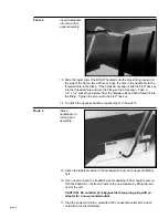
Align the tab on the side of the ribbon cable connector with its correspond-
ing receptacle. (See Photo 1 on the next page.) Connect the ribbon cable
by making sure that all the pins are aligned and fully engaged.


