background image

+1.866.977.7326 

www.preco.com  

3700042D 

Copyright 2016 

Page 16


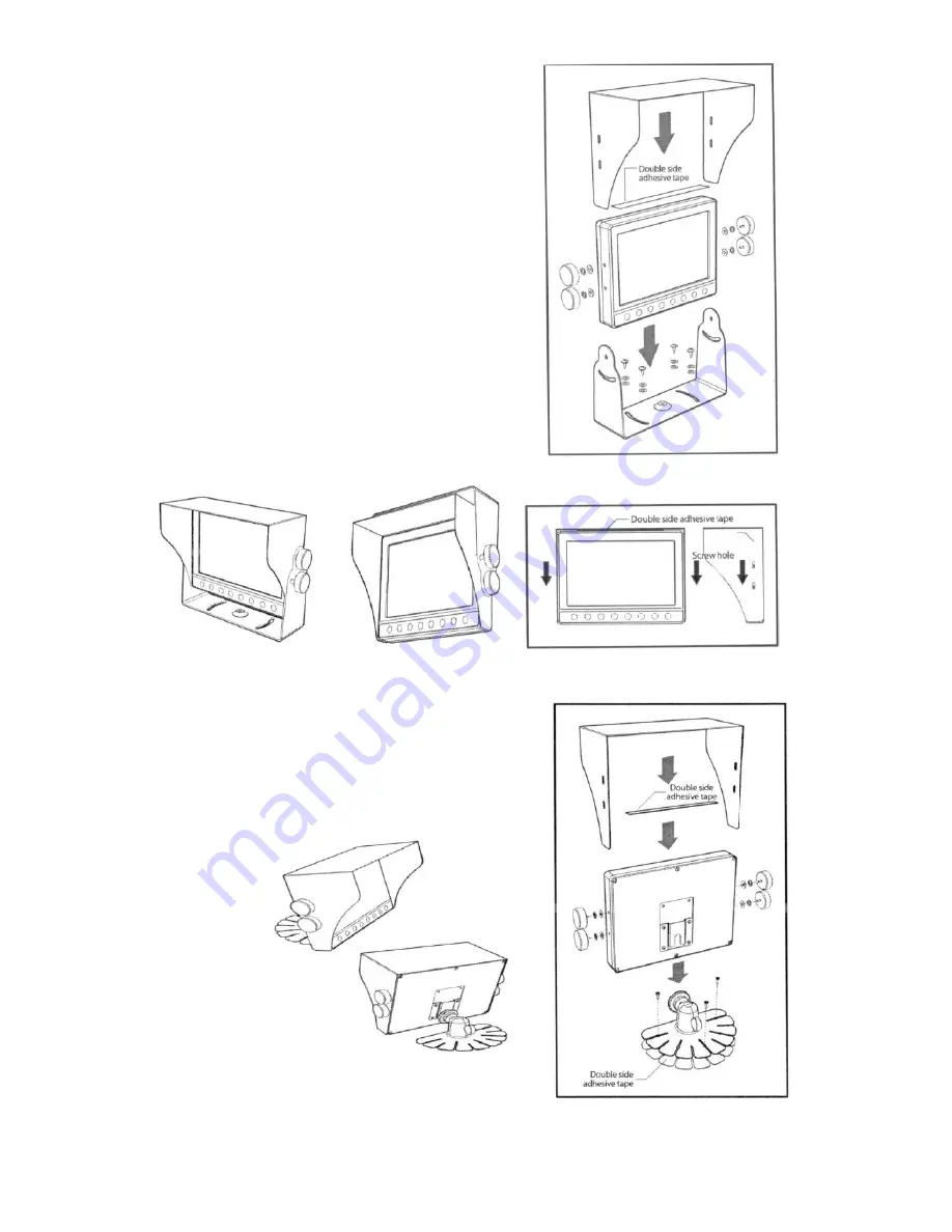
Bracket Installation 
 
Installation (U-Bracket) 
 

1.


Be sure to place the monitor away from  
heat sources.  Install the monitor stand  
with the enclosed screws and double  
sided tape as shown in the picture. 

2.


Fix the monitor to the monitor stand firmly. 


Installation (stand) 
 

1.


Be sure to place the monitor away from  
heat sources.  Install the monitor stand  
with the enclosed screws and double sided  
adhesive tape as shown in the picture. 

2.


Fix the monitor to the monitor stand  
firmly. 


Standard 

Installation 

Ceiling 

Installation 

Sun Visor should be installed 

with 4 screws. 

Summary of Contents for PreView Plus

Page 1: ...PreView Plus Monitor PVP710 Setup Guide www preco com...

Page 2: ......

Page 3: ...TRADEMARKS The names of actual companies and products mentioned herein may be the trademarks of their respective owners Any rights not expressly granted herein are reserved...

Page 4: ......

Page 5: ...ion with the PVP710 9 Configuring the PVP710 9 Understanding Sensor IDs 12 Detections Triggers 12 Setting up Camera Views Volume 13 Locking Out the Monitor Set the Home Screen 14 Standby Feature 15 Al...

Page 6: ...an object Safeguard Instructions Please read the following cautions carefully before using this product Following these rules prevent users from damages related to the misuse of the product Caution o...

Page 7: ...compatibility Multiple display modes single 2 3 4 split Automatic dimmer sensor 7 inch WVGA 800x480 Wide LCD Panel Automatic trigger for displays 4 Contents Before using this product please check the...

Page 8: ...and cycle through the different camera views 6 Left Right Buttons Used to change values for the different menu functions 7 Menu Button The menu button activates the on screen display OSD menus for mo...

Page 9: ...of the object being detected with red representing closest proximity This icon will appear in the event of a PreView radar sensor reporting a BIST Built In Self Test error If this icon appears the sys...

Page 10: ...e selected Dimmer sensor setting 1 Press the or button to select the value to change and change the value DAY brighter NIGHT darker AUTO sensor by pressing the or button Alternately pressing the butto...

Page 11: ...by pressing the or button Language selection English French German Italian Spanish Reset 1 Press the or button to move to RESET and then press button This will reset the settings to the factory defau...

Page 12: ...s the green V logo informing the operator that the sensor associated with that camera is powered and not detecting an object Also notice that the bottom screen has no symbol indicating that the sensor...

Page 13: ...communicate with one PreView sensor These instructions will guide you through the process of further configuring the PVP710 for this purpose and also explain how to set up multiple cameras and sensor...

Page 14: ...eing used in a reversing application Configuring the PVP710 The monitor is configured from the factory to communicate with a single rear sensor with an ID of 1 linked to Camera 1 Follow the next few s...

Page 15: ...ed cursor left or right to select the cell to change and buttons increment or decrement the sensor identification number see Understanding Sensor IDs on the next page for more information Up to six di...

Page 16: ...he Sensor Setup Menu should look like this once the IDs are entered To exit press the button until the Exit Sensor Setup Menu is highlighted and then press the button Or alternately the button can be...

Page 17: ...limited to numbers between 1 and 24 The same sensor ID cannot be assigned to multiple cameras Detections Triggers Detections and triggers are two different types of events that can cause the monitor...

Page 18: ...views available ranging from a single full screen view to several split screen views showing up to 4 cameras at the same time One of these views needs to be chosen to be set as the home screen The hom...

Page 19: ...nfirm lock out mode Whatever camera view is being displayed when the monitor enters lock out mode will be set as the home screen The home screen is important because it dictates what screen the monito...

Page 20: ...After either of these conditions clear the monitor will automatically go back into standby mode Standby mode can also be exited at any time by pressing the button again Alarm Acknowledge ACK Feature T...

Page 21: ...ews and double sided tape as shown in the picture 2 Fix the monitor to the monitor stand firmly Installation stand 1 Be sure to place the monitor away from heat sources Install the monitor stand with...

Page 22: ...1 866 977 7326 www preco com 3700042D Copyright 2016 Page 17 Connection CAN Bus Connector DC 12 24V Cam 4 Trigger Cam 3 Trigger Cam 1 Trigger Cam 2 Trigger Cam 4 Cam 3 Cam 2 Cam 1 RX...

Page 23: ...DC12V monitor set only Input System NTSC PAL Frequency NTSC H 15 734 kHz V 59 94 Hz PAL H 15 625 kHz V 50 Hz Input Signal Video Signal Composite Video CVBS Audio Signal Mono Speaker 0 5Watt max Langu...

Page 24: ...19 Troubleshooting For questions call 1 844 787 2327 toll free in the USA Call 1 208 323 1000 or send a fax request to 1 208 323 1034 for outside the USA or submit an online request at www preco com c...

Page 25: ...is detected PreView triggers the back up alarm to either increase the sound of the alarm OR change the beep rate to alert pedestrians outside of the vehicle of the danger Custom System Configurations...

Page 26: ...LAR PURPOSE ARE HEREBY EXCLUDED AND SHALL NOT APPLY TO THE PRODUCT BUYER S SOLE AND EXCLUSIVE REMEDY IN CONTRACT TORT OR UNDER ANY OTHER THEORY AGAINST MANUFACTURER RESPECTING THE PRODUCT AND ITS USE...

Page 27: ......

Page 28: ...Proudly developed by 10335 W Emerald St Boise Idaho 83704 www preco com 1 866 977 7326 3700042D...

Reviews: