26
PM-236 v4 -207.indd
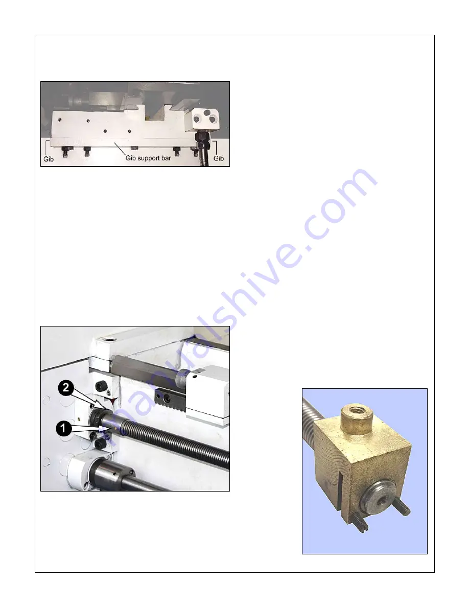
of the lathe. It comprises a support bar, attached to the
carriage, and two separate gib strips each with two ad-
justing screws.
Figure 4-2
Carriage gib assembly
LEADSCREW
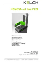
The shear pin, () in Figure 4-3, is designed to mini-
mise damage if the carriage encounters an obstruction
when traversing under leadscrew power. [If that should
occur when the carriage is powered instead by the
feed shaft, the drive is automatically disengaged by the
clutch, bottom of Figure 4-2, also Figure 3-5.] If the
shear pin breaks, use a /8" drift to clear remaining frag-
ments, and replace the pin with a 5/32" brass rod. When
hammering on the drift
avoid damage
to the gearbox
ouput shaft by placing a solid support block under the
leadscrew collar.
Figure 4-3
Leadscrew shear pin & end float adjustment
If the leadscrew develops end-float — can be moved
side to side by hand more than a few thousandths — this
is correctable by adjusting the spanner nuts (2) in Fig-
ure 4-2. If a suitable C-spanner is not available use a
soft metal (brass) drift and light hammer taps to free the
outer (lock) nut. Adjust the innner nut to take up the end-
float, then re-tighten the lock nut.
Split nut adjustment
If the split nut becomes excessively loose, with appre-
ciable side to side movement, this may be corrected
by adjusting the gib at the back of the apron, item 67
on the apron schematic, Section 5. Loosen screws 68
holding the gib to the apron casting, then tighten the gib
by screws 72 (left of the threading dial assembly). Re-
tighten the securing screws and lock nuts.
CROSS SLIDE BACKLASH
When alternating between clockwise and counter
clockwise rotation of the cross slide leadscrew, the
handwheel moves freely a few degrees but the cross
slide table stays put. The acceptable amount of lost
motion depends on the user, but 0.005” is generally a
good compromise. Smaller numbers are possible, but
overdoing it can lead to premature wear of leadscrew
and nut.
Excessive backlash in the cross slide can be corrected
by expanding the leadscrew nut, Figure 4-4. Referring
to the carriage schematic, Section 5, remove the socket
head screw 6 securing the cross slide to nut 20. Turn
the handwheel counter-clockwise (this is a LH lead-
screw) to drive the nut backward to the point where the
two set screws at the back the nut are accessible. Use
a flat-blade screwdriver turned clockwise to expand the
gap, tightening the nut.
The compound leadscrew nut is not adjustable.
Figure 4-4
Carriage leadscrew nut


