7
PM-236 v4 -207.indd
COMPOUND SETUP FOR THREAD CUTTING
Thread cutting on the lathe is unlike most other turning
operations, for two reasons: . The cutting tool must be
precisely ground with an included angle of 60 degrees
for most American and metric threads, and; 2. It is pref-
erable to feed the tool into the workpiece at an angle so
it cuts mostly on the left flank of the thread. The correct
angle relative to the cross slide (zero degrees) is a sub-
ject of debate — should it be 29, 29-/2 or 30 degrees?
Many machinists prefer 29 degrees because it holds
the cutting tool marginally clear of the right flank of the
thread, close enough for cleanup of the flank while at the
same time avoiding appreciable rubbing.
The 45
o
- 0
o
- 45
o
scale on the compound is not directly
helpful in setting the thread cutting angle, but it can be
used for that purpose if a second reference mark is ap-
plied to the cross slide. First make certain that the com-
pound is truly aligned with the lathe axis when 0
o
on the
scale is on the cross slide reference mark — do this by
indicating against a ground bar between centers while
advancing the indicator using only the compound. Allow
for the variance, if any, when applying the new reference
mark. Grind a chisel edge on a /4 in. square HS tool bit,
align it precisely on the left hand 30
o
scale mark; then,
wearing safety glasses, rap the tool bit sharply with a
hammer.
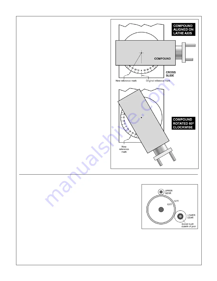
Figure 3-7
Setting up the compound for 30
o
infeed
A new reference mark is stamped on the cross slide at 30 de-
grees. To set the compound for thread cutting, rotate it clock-
wise to bring the right hand 30
o
scale mark in line with the new
reference mark. For 29
o
rotate the compound 1 degree more.
CHANGE GEARS FOR THREAD CUTTING
The large gears in Figure 3-2 are
transposing gears
,
20T and 27T. They allow a standard-thread leadscrew,
in this case 8 tpi, to cut metric threads. The transposing
gears are keyed together.
Key facts to remember
:
For U.S. thread cutting, the 27T larger gear is simply
an
idler
, transferring the drive from the upper gear to the
lower gear. In this configuration, the spacer bushing is
outside
the lower gear, as Figure 3-2.
For metric thread cutting, the lower gear is driven by the
20T transposing gear. In this configuration, not shown,
the spacer bushing is
inside
the lower gear.
Any change to the drive train typically calls for one or
both of the upper and lower gears to be exchanged for
For all TPI standard
threads (U.S.A.) the
127T gear is an idler
between upper and
lower gears.
by a larger or smaller gear. This will require the trans-
posing gear pair to be repositioned. The procedure for
this is:
Remove the M6 socket head screws from the upper
•
Figure 3-8
Standard TPI setup


