


4
Copyright © 2020 Quality Machine Tools, LLC
PM-1228VF v3 2020-10
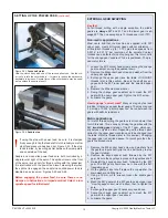
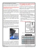
The mounts shown in Figure 1-3, available from Precision Mat-
thews, allow leveling adjustment from above. If installing on
the PM1228 stand, 8 leveling mounts are required — 4 for the
left hand cabinet, 4 for the right. Because there is insufficient
headroom in the stand pockets, the threaded stems need to be
shortened by about 1-1/2”. Before installing, oil the threads in
each mount then bottom the stem (8 mm wrench) to be sure
the pressure plate is able to expand the molded base. If neces-
sary use a strap wrench to stop the cup from rotating.
Place the cup under the stand, with washer and locknut
above
the stand footplate. Because an 8 mm wrench has only a small
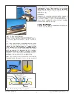
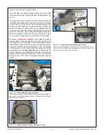
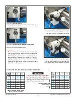
Figure 1-2
Check level in both axes
Check level of the cross-slide at headstock and tailstock ends — if
there is no twisting of the bed the indication should be the same. To
check the left to right axis rest the level on a precision ground bar, as
here.
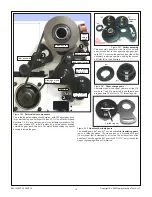
Figure 1-3
Top-adjusting leveling mount
(optional)
Pusher plate
Washer
M12 x 1.75 x 50 mm
hex head screw
Molded base
Locknut
Stand footplate
Cup stamping
Weld nut
amount of leverage, it may be more convenient to replace the
threaded stems with hex head screws (M12 x 1.75). Screw
length should be 50 mm, but 45 mm (even 40 mm) will do
if the floor is reasonably level. Adjust using a 19 mm or 3/4”
ratcheting wrench.
CLEANUP
Finished metal surfaces may be protected by thick grease and/
or paper. Carefully remove these using a plastic paint scrap-
er, disposable rags and a light-oil such as WD-40. Be sure to
remove paint over-spray from surfaces that may affect sliding
motion, such as under the bed ways.
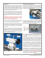
POWER REQUIREMENT
Plug the supplied cord into a standard 110V ac outlet,
minimum capacity 20 Amps.


