


28
Copyright © 2020 Quality Machine Tools, LLC
PM-1228VF v3 2020-10
SUGGESTED PROCEDURE: CROSS-SLIDE SCALE
*
If the saddle was removed for milling, the back surface can be drilled
and tapped on drill press or mill, Figure D. Otherwise, the back surface
is drilled with the saddle in place.
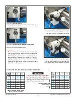
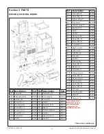
Figure G
Limit mark on scale
Note the punch mark on the scale
above the arrow on the reading head
Figure F
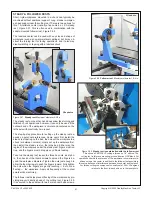
Aligning the support plates
One of two temporary standoffs is behind the square
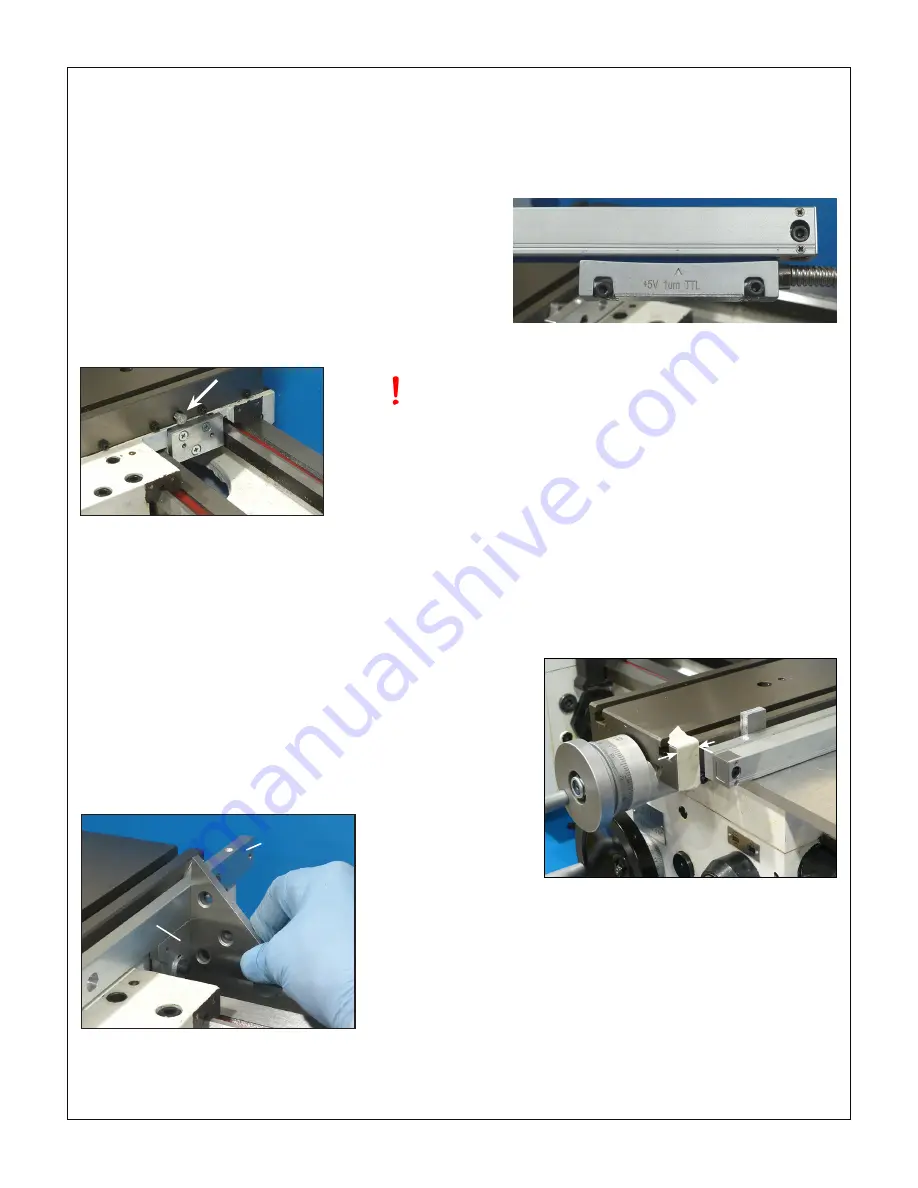
Figure H
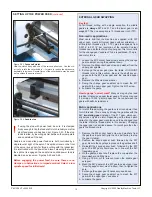
Scale set-back
Masking tape shows the approximate location. This must be mea-
sured precisely if the support plate doesn’t have slotted holes to allow
trial and error front to back positioning.
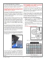
Figure E
Standoff block for reading head
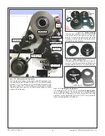
A 3/16
″
diameter steel ball was inserted between the gib and the
replacement hex head
cross-slide lock screw (M6 ) shown here,
arrowed. The ball applies pressure more evenly on the gib.
1.
Fabricate the 1/4″ thick replacement reading head support
plate shown in Figure A. The slots are not counterbored,
so can be filed.
2.
Drill and tap two or more M5 (or 10-32) holes in the well
area on the right hand side of the saddle, Figure C. (If you
are doing this with the saddle in place, see the separate
lathe DRO installation note from Precision Matthews.) For
the installation illustrated here the saddle was removed
and milled as Figure C for a flat, vertical surface.
*
Three
tapped holes is overkill if the surface is milled as shown
— but probably not if the reading head plate is to be trued
using shims or jacking screws instead.
3.
Fabricate a 3/8″ thick standoff block with counterbored or
countersunk holes, as Figure E. Drill and tap two tapped
M5 (or 10-32) holes to match the slots in the reading head
support plate.
4. Attach the standoff block to the saddle. Check that the
block surface is truly at right angles to the top surface of
the cross-slide, and in line with the cross-slide, front to
back.
This is important!
Shim as necessary.
5. Loosely attach the reading head support plate to the
standoff block (skt heads and washers).
6. This step determines how thick to make the standoffs be-
tween cross-slide and the scale support plate. The outface
of the scale support plate should be perfectly aligned with
the reading head support plate, Figure F. In the example
installation the temporary standoffs, one at each end of
the scale support, were about 0.3” thick, a combination
of 1/4″ plate and shims. They were held in place on the
cross-slide using thin double-sided tape.
7. Attach the reading head to its support plate with two M4
skt heads, preferably with lock washers. Attach the read-
ing head support plate loosely to the standoff block on
the saddle.
Careful handling is needed here to avoid
stressing the interface between head and scale
8. Temporarily install the scale on its support plate with two
M4 skt heads.
9. Note the markings on scale and reading head, Figure G.
The photo shows full travel of the head to the right. Push-
ing it beyond this point, or the corresponding point at the
other end, may damage the DRO.
10. With the temporary standoffs in place between the scale
support plate and the cross-slide, crank the cross-slide
handle counter-clockwise to bring the cross-slide fully to-
ward you — dead stop. Gently ease the scale forward as
far as it will go, watching out for the limit mark. Measure
the set-back between the front face of the cross-slide and
the end of the scale, Figure H.
This is important
— it
sets the location of the scale support plate relative to the
cross-slide. In the example installation the set-back was
0.75″. If you have a mill, and can slot the scale support
plate, Figure B, the set-back measurement is not critical.
Not so if you are installing by dead reckoning, holes in-
stead of slots.
11. Remove the scale and reading head. Modify the scale
support plate with two new slotted holes, if able, then drill/
tap the cross-slide to suit (the hole locations in Figure B
are clear of the T-slots).
In the example installation, the
cross-slide was removed and processed on a mill.
12. With the temporary standoffs in place, secure the scale
support plate to the cross-slide, then re-test for vertical
alignment, Figure F. Determine the exact thickness of the
finished standoffs using feeler gages.
13. Fabricate the finished standoffs. Those shown in Figure J
Scale support
plate
Reading head
support plate
Instead of milling
the right hand sur-
face of the saddle,
jacking screws in
the standoff block
can be used to set
the block vertical