26
Copyright © 2020 Quality Machine Tools, LLC
PM-1228VF v3 2020-10
ADJUSTMENT — SPINDLE BEARINGS
The spindle runs on two grease-packed precision bearings,
a tapered roller bearing at the nose, and a deep-groove ball
bearing at the pulley end. They are factory adjusted, and
should need no attention. If end play becomes evident (work
-
piece chatter, poor finish, etc.), this can be corrected by tight
-
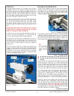
ening the spindle locknut, Figure 4-12. To do this, loosen the
two clamp screws, proceed as follows:
The item numbers refer to Figure 4-16 and also the Headstock
parts diagram
1. Remove the chuck or other work holding device from the
spindle.
2. Disengage the external gear train and remove the Vee belt.
3.
Using a 3 mm hex key, remove the two flat-head screws,
item #251 (removing the screws allows the compressible
locknut #281 to turn).
4. Unscrew locknut #281 one full turn.
5.
Place a scrap wooden block about 3/4″ thick over the left
hand end of the spindle.
6. Strike the block with a heavy dead-blow hammer. The in-
tention is to drive the spindle forward just enough to intro-
duce end float detectable by hand.
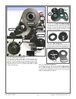
7. Using the supplied pin wrench located in the arrowed holes,
Figure 4-16), re-tighten the locknut to the point where the
spindle rotates (by hand) with noticeable resistance.
8.
Back off the nut a few degrees then check spindle rotation
again.
9. Re-loosen and re-tighten a few times to achieve the best
compromise, then re-compress the locknut with the two
flat-head screws.
10. Re-attach the Vee belt. Run the motor for a few seconds to
check for smooth/quiet operation.
11. Run the motor for a lengthy period, say 15 minutes, then
check the temperature of the spindle nose. It should be just
warm to the touch, no hotter than that.
If hotter than the “just warm” spec, the bearings are too heavily
pre-loaded. Back off the spindle locknut, then repeat the 15
minute temperature test..
ADJUSTMENT — LEADSCREW END FLOAT
ADJUSTMENT — LEADSCREW SPLIT-NUT
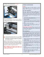
Figure 4-14
Split-nut adjustment
M5 socket head cap screws, 8 mm locknuts
Upper and lower split nuts run in vertical dovetails in the apron,
see part(s) #605 in the Apron parts diagram. The split-nut le
-
ver at the front of the apron should move smoothly, but with
a small degree of resistance. If is becomes noticeably loos-
er over time, this can be corrected by tightening the screws
shown in Figure 4-14.
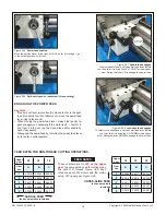
Adjust the leadscrew and feed shaft for minimal end float (side
to side movement) without noticeable binding. Loosen the out
-
er locknut; tighten the inner nut to press the flat washer firmly
against the support bracket, then back off about 45 degrees.
Re-tighten the locknut .
19 mm
17 mm
Figure 4-15
End float adjustment
Figure 4-16
Pin wrench for spindle locknut
The inside rim of the wrench may need easing with a file or grinder
Screw
#251
Locknut
#281


