background image

P

RO

V

U

™ PD6088/PD6089 Modbus

®

 Scanner 

Instruction Manual 


55 

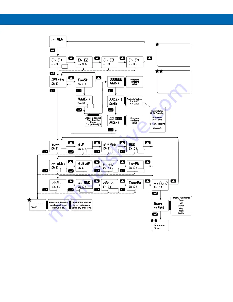
Math Function Menu (

nmath


Notes: 

1. 

In the above menu, “A” & “B” in equations can represent any PVs (PV1-PV16). See table above. 

2.  Each digit represents one PV in hexadecimal format, except PV16 (G). 

3.  PV1 

– PV9 = 1 - 9, PV10 – PV16 = A – G 

4. 

No PV selected = “underscore symbol” 

5.  Digit range: 1-

G, then “_” 

6.  If there is an empty digit, the scanner will end the equation at that point. 
7. 

For Math2 Channel, “C” is fixed, indicating which Math Channels are being processed. 

8.  Please refer to the following graphics for details on various Math Functions: 

Main Math Channels:

Each PV is represented by an

underscore. There are 6 lines

shown and ten lines hidden.  Enter

any or all PVs without leaving a

space. Any spaces will signal the

meter to end the equation there.

Move to the next PV by pressing

the Up Arrow.

C

A+B

A-B

abs
A-B

(A+B)/2

A*B

A/B

Max

Min

((A/B)-1)*F

((B-A)*F)+A

(A/B)*F

(A/(A+B))*F

P

F

Math2 Channel:

Each Math Channel C1, C2, C3, C4 is

represented by an underscore. There

are 4 lines shown for most equations,

two for others. Enter any or all Math

Channels without leaving a space.

Any spaces will signal the meter

to end the equation there. Move to

the next PV by pressing the Up Arrow.

Summary of Contents for PROVU PD6088 Modbus

Page 1: ...ransmitter Power Supply 2 or 4 Relays with Interlocking Capability Isolated 4 20 mA Output Options Free PC Based On Board ScanView USB Programming Software SunBright Display Standard Feature Great for...

Page 2: ...omplete details Registered Trademarks All trademarks mentioned in this document are the property of their respective owners 2020 Precision Digital Corporation All rights reserved FREE ScanView Program...

Page 3: ...mmunications Connections Table 16 F4 Digital Input Connections 16 Relay Connections 17 Switching Inductive Loads 17 4 20 mA Output Connections 17 Analog Output Power Supply 17 External Relay Analog Ou...

Page 4: ...43 Fail Safe Operation failsf 43 Front Panel LEDs 43 Latching and Non Latching Relay Operation 43 Non Latching Relay Auto 44 Non Latching Relay with Manual Reset A nman 44 Latching Relay LatcH 44 Lat...

Page 5: ...re 6 PD6088 89 H2 Connectors Label 15 Figure 7 PD6088 89 H3 Connectors Label 15 Figure 8 PD6088 89 H4 Connectors Label 15 Figure 9 PD6088 89 H5 Connectors Label 15 Figure 10 PD6088 89 H7 Connectors La...

Page 6: ...ponent or round horizontal tank calculations The displays relays and the analog outputs may be assigned to PVs or to math channels C1 C2 C3 or C4 The digital inputs outputs can be custom programmed fo...

Page 7: ...oper mode Time the scanner will wait for new data before going into break condition Slave mode Programming 0 disables the timeout the last value received will be displayed indefinitely Communica tion...

Page 8: ...ed in non volatile memory for a minimum of ten years with or without power Power Options 85 265 VAC 50 60 Hz 90 265 VDC 20Wmax 12 24 VDC 12 24 VAC 15 W max Powered over USB for configuration only Fuse...

Page 9: ...or each relay Note Relay coil is energized in non alarm condition In case of power failure relay will go to alarm state Auto Initialization When power is applied to the scanner relays will reflect the...

Page 10: ...lete list of capabilities Contacts 3 3 VDC on contact Connect normally open contacts across F4 to COM Logic Levels Logic High 3 to 5 VDC Logic Low 0 to 1 25 VDC Additional I O Up to 2 external modules...

Page 11: ...80 MHz 1kHz 80 AM AC Surge 2kV Common 1kV Differential Surge 1KV CM Power Frequency Magnetic Field 30 A m 70 V for 0 5 period Voltage Dips 40 V for 5 50 periods 70 V for 25 periods Voltage Interruptio...

Page 12: ...de the bracket toward the front of the case and remove Insert scanner into the panel cutout Install mounting brackets and tighten the screws against the panel To achieve a proper seal tighten the moun...

Page 13: ...8 Install the scanner and put into service 9 Make any programming adjustments using the front panel buttons ScanView Software The easiest and quickest way to program your PROVU scanner is to use the...

Page 14: ...ou receive a User Account Control warning click Yes 4 If there is an update available click the Update button to install the new version Otherwise click Configure to begin programming your scanner Not...

Page 15: ...nectors Label Figure 10 PD6088 89 H7 Connectors Label DO NOT connect any equipment other than Precision Digital s expansion modules cables or scanners to the RJ45 M LINK connector Otherwise damage wil...

Page 16: ...ions for 3 wire RS 485 devices PD6088 PD6089 Master PD6088 PD6089 Snooper PC Connection Modbus Slave Meter Modbus Level Gauge On Board Terminals On Board Terminals PDA8485 RS 485 to USB RS 485 RS 485...

Page 17: ...rminals An RC network may also be installed across the load Experiment for best results Use a diode with a reverse breakdown voltage two to three times the circuit voltage and forward current at least...

Page 18: ...re As the name implies the interlock relay feature reassigns one or more alarm control relays for use as interlock relay s Interlock contact s are wired to digital input s and trigger the interlock re...

Page 19: ...F Communications Fault Condition PAUSE Press SCAN to pause scanning PLAY Press SCAN to resume scanning STOP Stop scan on alarm Note LEDs for relays in manual mode flash with the M LED every 10 second...

Page 20: ...Byte Order Select little endian byte order 2143 Byte Order Select byte swapped big endian byte order Not available for Short integer Display Functions Messages Display Parameter Action Setting Descri...

Page 21: ...nd setup Setup Enter Setup menu pV Process Variable Enter PV Setup menu PV 1 PV Select PV 1 16 tag Tag Tag units Units Units Display Functions Messages Display Parameter Action Setting Description for...

Page 22: ...Relay turns on when Communications Break detected Off Off Relay goes to non alarm condition when break detected Relay turns off when Communications Break detected Display Functions Messages Display Pa...

Page 23: ...ext digit and the Up arrow to increment the digit s value The digit being changed is displayed brighter than the rest Press and hold the Up arrow to auto increment the display value Press the Enter bu...

Page 24: ...unique address The scanner address Scan ID may be programmed between 1 and 247 The transmit delay may be set between 0 and 4999 ms this value must be less than Poll Time of PVs The parity can be set...

Page 25: ...Enable Process Variables PVs In Master or Snooper Mode navigate to the PV Number menu and press ENTER From there the user can scroll through all of the sixteen available PVs In order to enable a speci...

Page 26: ...Poll Time and Response Timeout menus PV Number Enable disable PVs select slave ID function code register number data type byte order Poll Time Enter the time interval to poll the slave devices selecte...

Page 27: ...ibility of communication errors and communication break conditions use a poll time of 5 seconds or more with slow baud rates e g 4800 bps or less 2 The response time for scanners set up for Snooper mo...

Page 28: ...Type is Float 3 Default Slave ID for PV1 001 for PV2 002 for PV3 003 etc The Master ignores the decimal point setting for slave devices that specify a Short or Long integer For example a slave that is...

Page 29: ...etup The Setup menu is used to select 1 PV Setup a PV Tags b PV Units c Format Decimal point or Feet Inches d Decimal Point e Scale input data 2 Display assignment Intensity 3 Relay assignment and ope...

Page 30: ...tag units format display decimal point float decimal point resolution and scaling of the input data Note PV1 and PV2 can have multiple points for linearization Only two points are available for all ot...

Page 31: ...ut 2 must be less than Input 3 etc known as monotonic values Press Enter to save the changes or Menu to exit without saving When the Linear function is selected for PV1 PV2 up to 32 points may be prog...

Page 32: ...ogrammed to display any of the following Display Parameter Setting Description D pV Display PV Display PVs 1 16 D Ch C Display C Channel Display Math Channels C1 C4 PV unit Display PV Units Display PV...

Page 33: ...nner Instruction Manual 33 Display Line 1 Menu Line 1 dsplay Note For Tag PVn and Tag PVn U the default settings for PVs are 1 3 5 7 followed by two underscores which represent empty PVs These all can...

Page 34: ...nner Instruction Manual 34 Display Line 2 Menu Line 2 dsplay Note For Tag PVn and Tag PVn U the default settings for PVs are 2 4 6 8 followed by two underscores which represent empty PVs These all can...

Page 35: ...e right are shifted one position Press and hold up arrow to auto scroll the characters in the display Application Example 1 In this application we have a system consisting of 4 multivariable tank leve...

Page 36: ...ster PV6 30017 30017 Tank 2 Average Temperature Data Type Long integer Binary Signed Long Byte Order 1234 1234 PV7 Slave ID 3 3 Parameter PD6088 Master PD6088 Snooper Description Comment Function Code...

Page 37: ...l Interface Display 1 000000 000000 Input 2 999999 999999 0 001 inch resolution Display 2 83 333 83 333 Feet Application Example 2 In this application we have a system consisting of 4 multivariable ta...

Page 38: ...dition has cleared e Pump alternation control automatic reset only f Sampling the relay is activated for a user specified time g Off relay state controlled by Interlock feature 3 Set 1 Set point Rst 1...

Page 39: ...w the set point Note Changes are not saved until the reset point has been accepted Setting Fail Safe Operation failsf In fail safe mode of operation the relay coil is energized when the process variab...

Page 40: ...mer resets and the relay does not change state The same principle applies to the Off time delay Note If Automatic or Manual A nmAn reset mode is selected the LED follows the reset point and not the re...

Page 41: ...t go below the set point and then go above it Low Alarm Operation Set Reset For Manual reset mode ACK can be pressed anytime to turn off relay For relay to turn back on signal must go above set point...

Page 42: ...f or on based on their operating mode and their set and reset points without regard to their prior state This is similar to the auto initialization on power up Below is a diagram showing three example...

Page 43: ...Ds The LEDs on the front panel provide status indication for the following LED Status LED Status 1 Alarm 1 5 Alarm 5 2 Alarm 2 6 Alarm 6 3 Alarm 3 7 Alarm 7 4 Alarm 4 8 Alarm 8 The scanner is supplied...

Page 44: ...Manual reset any time Condition LED Relay Normal Off Off Alarm On On Ack Off Off Latching Relay with Clear Lt Clr In this application the scanner is set up for manual reset only after the signal passe...

Page 45: ...the set and reset points of pump 2 outside the range of pump 1 the first pump on is the first pump to go off This is true for up to 8 alternating pumps if set up accordingly 6 Relay 3 will go into ala...

Page 46: ...urce Programming aoutpr on page 58 No equipment is needed to scale the analog outputs simply program the display values to the corresponding mA output signal The Analog Output menu is used to program...

Page 47: ...is being displayed and enter the correct password to gain access to the menu After exiting the programming mode the scanner returns to its password protected condition Disabling Password Protection T...

Page 48: ...de time Scan Time Select Scanning Time nman Manual Select Manual Scan Mode Alarnm Alarm Select Go or Stop Alarm go Go Select Alarm Go Stop Stop Select Alarm Stop Contrl Manual Control Enter Manual Con...

Page 49: ...to other math channels e g C3 C1 C2 sunm Sum Math2 Function Sum dif Difference Math2 Function Difference Advanced Features Menu Display Messages Display Parameter Action Setting difabs Absolute Diffe...

Page 50: ...he PV scan mode and the scanner s behavior on alarm condition The operator is able to scan automatically based on a time parameter or scan manually with front panel keys or digital inputs The operator...

Page 51: ...own the display response to changes on the input signal This parameter is associated with the analog input channels Rounding Feature round The rounding feature is used to give the user a steadier disp...

Page 52: ...level transmitters used to measure volume in odd shaped tanks or to convert level to flow using weirs and flumes with complex exponents Note Multi point Linearization applies to PV1 and PV2 only All...

Page 53: ...The tank s dimensions can be entered in inches or centimeters the scanner automatically calculates the volume in gallons or liters After entering the dimensions complete the scaling process with the d...

Page 54: ...bS Average PV1 PV2 2 P F AVG Multiplication PV1 PV2 P F Nmulti Division PV1 PV2 P F diVide Max PV Max value of all selected PVs Hi pV Min PV Min value of all selected PVs Lo pV Draw PV1 PV2 1 F drAuw...

Page 55: ...se refer to the following graphics for details on various Math Functions Main Math Channels Each PV is represented by an underscore There are 6 lines shown and ten lines hidden Enter any or all PVs wi...

Page 56: ...Modbus Scanner Instruction Manual 56 Sum Menu sunm Difference Menu dif Difference Absolute Menu difAbS Average Menu aVg Multiplication Menu nmulti Divide Menu diVide Only two PVs at a time will be use...

Page 57: ...raw Menu drauw Only two PVs at a time will be used for this function Weighted Average Menu uwAvg Only two PVs at a time will be used for this function Ratio Menu ratio Only two PVs at a time will be u...

Page 58: ...log outputs can be programmed for source of data overrange and underrange absolute maximum and minimum output and communications break values They can also be recalibrated To calibrate the analog outp...

Page 59: ...that includes a power supply internal or external 12 to 24 VDC and the mA input on the digital meter See Figure 18 4 20 mA Output Connections on page 17 for details 2 Turn on all devices Allow for a...

Page 60: ...he stored maximum minimum display values for all channels relay Directly access the relay menu Set 1 Directly access the set point menu for relay 1 through 8 Rly d Disable all relays until a button as...

Page 61: ...you to the next level then pressing the Up arrow until you arrive at the RESET menu Press ENTER to assign the RESET menu to the selected function key or digital input Now when the scanner is in Run Mo...

Page 62: ...es 3 Baud rate and parity of all devices on the bus 4 Scanner Id must be different from other devices Snooper mode not reading the PVs on the RS 485 bus Check 1 Increase Master s Transmit Delay e g Sn...

Page 63: ...Mode after displaying all the settings Reset Scanner to Factory Defaults When the parameters have been changed in a way that is difficult to determine what s happening it might be better to start the...

Page 64: ...nnel on the upper display and alternate between tag units on the lower display The relays and analog output can be programmed to operate based on any PV or math channel Front Panel Buttons Operation B...

Page 65: ...1 4 Sunm Sum Adder constant P Adder 0 000 Factor constant F Factor 1 000 Factory Defaults User Settings Parameter Display Default Setting Filter Filter Filter PV 1 Ch A 70 Filter PV 2 Ch B 70 Bypass P...

Page 66: ...ange output O rang 21 000 mA Underrange output u rang 3 000 mA Communications break output break 1 000 mA Maximum output nmAx 23 000 mA Minimum output nmin 1 000 mA F1 function key F1 Previous PV F2 f...

Page 67: ...plicable technical standards and when applicable or required a European Union notified body certification Standards EN 55022 2003 EN 61000 6 2 2001 EN 61010 1 2001 EN 61326 2006 The standards EN 55022...

Page 68: ...w predig com LIM6088_F SFT088 Ver 2 020 up 05 20 Contact Precision Digital Technical Support Call 800 610 5239 or 508 655 7300 Fax 508 655 8990 Email support predig com Sales Support Call 800 343 1001...

Reviews: