P
RO
V
U
PD6210 Analog Input Batch Controller Instruction Manual
7
Programmabl
e Exponent
1.0001 to 2.9999
Low-Flow
Cutoff
0-999999 (0 disables cutoff function)
Decimal Point
Up to five decimal places or none:
d.ddddd
,
d.dddd
,
d.ddd
,
d.dd
,
d.d
,
or
dddddd
Calibration
Range
Input Range Minimum Span
Input 1 & Input 2
4-20 mA
0.15 mA
10 V
0.01 V
An error message will appear if the input 1
and input 2
signals are too close together.
Input
Impedance
Voltage ranges: greater than 500 k
Current ranges: 50 - 100
(depending on
resettable fuse impedance)
Input
Overload
Current input protected by resettable fuse,
30 VDC max.
Fuse resets automatically after fault is
removed.
F4 Digital
Input
Contacts
3.3 VDC on contact. Connect normally open
contacts across F4 to COM.
F4 Digital
Input
Logic Levels
Logic High: 3 to 5 VDC
Logic Low: 0 to 1.25 VDC
Batch Controller Rate/Totalizer Display
Rate Display
Indication
-99999 to 999999, lead zero blanking. “R”
LED illuminates while displaying rate.
Batch Total &
Grand Total
Display
0 to 999,999; automatic lead zero blanking.
“T” LED is illuminated while displaying batch
total. “GT” LEDs are illuminated while
displaying grand total. Up to 999,999 for
batch total/preset. Up to 999,999,999 with
grand total-overflow feature. “
oF
” is displayed
to the left of grand total overflow and ▲ LED
is illuminated.
Batch Total
Decimal Point
Up to five decimal places or none:
d
.
ddddd
,
d
.
dddd
,
d
.
ddd
,
d
.
dd
,
d
.
d
,
or
dddddd
Total decimal point is independent of rate
decimal point.
Totalizer
Calculates total based on rate and field
programmable multiplier to display total in
engineering units. Time base must be
selected according to the time units in which
the rate is displayed.
Grand
Totalizer
Rollover
Grand totalizer rolls over when display
exceeds 999,999,999. Relay status reflects
display.
Grand Total
Alarms
Up to seven, user selectable under setup
menu. Any set point can be assigned to
grand total and may be programmed
anywhere in the range of the controller for
grand total alarm indication. Relay 1 should
always be assigned to batch.
Programmabl
e Delay on
Release
0.1 and 999.9 seconds; applied to the first
relay assigned
to total or grand total.
If the controller is programmed to reset total
to zero automatically when the preset is
reached, then a delay will occur before the
total is reset.
Grand Total
Reset
Via front panel button, external contact
closure on digital inputs, automatically via
user selectable preset value and time delay,
or through serial communications.
Grand Total
Reset
Password
Grand total passwords may be entered to
prevent resetting the grand total from the
front panel.
Non-
Resettable
Grand Total
The grand total can be programmed as a
non-resettable total by entering the
password “050873”.
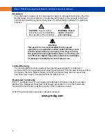
Caution!
Once the Grand Total has been
programmed as “non-resettable”
the feature
cannot
be disabled.
Relays
Rating
2 or 4 SPDT (Form C) internal and/or 4
SPST (Form A) external; rated 3 A @ 30
VDC and 125/250 VAC resistive load; 1/14
HP (
≈
50 W) @ 125/250 VAC for inductive
loads
Noise
Suppression
Noise suppression is recommended for each
relay contact switching inductive loads; see
page 14 for details.
Relay
Assignment
Relays may be assigned to batch control
total, sampling, rate, or grand total alarms.
Preclose
0-100% of batch size, individually user
programmable for each additional batch
control relay beyond the first.
Alarm
Deadband
0-100% of span, user programmable
High or Low
Alarm
User may program any alarm for high or low
trip point.
Unused alarm LEDs and relays may be
disabled (turn off).
Relay
Operation
Batch control
Automatic (non-latching)
1
Sampling
Off (disable unused relays and enable
Interlock feature)
Manual on/off control mode
Secondary Functions
2
Pump alternation control (2 to 8 relays)
Latching (requires manual acknowledge)
Relay Reset
User selectable via front panel buttons,
digital inputs, or PC
1. Automatic reset only (non-latching),
when the input passes the reset point
or total is reset to zero.
2. Aut manual reset at any time
(non-latching)
3. Manual reset only, at any time
(latching)
4.
Manual reset only after alarm condition
has cleared (L)
Note: Digital inputs may be assigned to
acknowledge relays programmed for manual
reset. It is not recommended to change the
functions of front panel buttons to manual
reset.
Alarm Time
Delay
0 to 999.9 seconds, on & off relay time
delays
Programmable and independent for each
relay.
!

