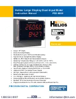
Helios Large Display Dual-Input Meter Instruction Manual
PD2-6060
6
Isolation
4 kV input/output-to-power line
500 V input-to-output or output-to-P+
supply
Overvoltage
Category
Installation Overvoltage Category II:
Local level with smaller transient
overvoltages than Installation
Overvoltage Category III.
Environmental
Operating temperature range: -40 to
150°F (-40 to 65°C)
Storage temperature range: -40 to 185°F
(-40 to 85°C)
Relative humidity: 0 to 90% non-
condensing
Connections
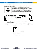
Removable and integrated screw
terminal blocks accept 12 to 22 AWG
wire.
Enclosure
UL Type 4X, IP65 rated. Polycarbonate
& glass blended plastic case, color:
gray. Includes four PG11 through-hole
conduit openings, with two factory
installed PG11, IP68, black nylon
threaded hole plugs with backing nuts.
Mounting
Wall Mounting:
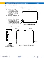
Four (4) mounting holes
provided for screwing meter into wall.
See Wall Mounting Instructions on page
10 for additional details.
Pipe Mounting:
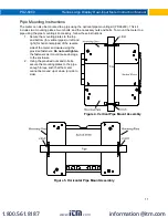
Optional pipe mounting
kit (PDA6260) allows for pipe mounting.
Sold separately. See Pipe Mounting
Instructions on page 11 for additional
details.
Tightening
Torque
Removable Screw Terminals:
5 lb-in
(0.56 Nm)
Digital I/O and RS485 Terminals:
2.2
lb-in (0.25 Nm)
Overall
Dimensions
10.63" x 12.59" x 4.77" (270 mm x 319.7
mm x 121.2 mm) (W x H x D)
Weight
6.10 lbs (2.76 kg)
Warranty
3 years parts & labor
Dual Process Input
Two Inputs
Two
non-isolated
inputs, each separately
field selectable:
0-20, 4-20 mA,
10 V (0-5, 1-5, 0-10 V),
Modbus PV (Slave)
Channels
Channel A, Channel B, Channel C (Math
channel)
Programmable
Constants
Constant P (Adder):
-99.999 to 999.999,
default: 0.000
Constant F (Factor):
0.001 to 999.999,
default: 1.000
Accuracy
±0.03% of calibrated span ±1 count,
square root & programmable exponent
accuracy
range: 10-100% of calibrated span
Temperature
Drift
0.005% of calibrated span/
C max from 0
to 65
C ambient,
0.01% of calibrated span/
C max from -40
to 0
C ambient
Signal Input
Conditioning
Linear, square root, programmable
exponent, or round horizontal tank volume
calculation
Math
Functions
Name
Function
Setting
Addition
(A+B+P)*F
Sunm
Difference
(A-B+P)*F
diF
Absolute diff. ((Abs(A-B))+P)*F
diFAbS
Average
(((A+B)/2)+P)*F
AvG
Multiplication ((A*B)+P)*F
nmulti
Division
((A/B)+P)*F
divide
Max of A or B ((AB-Hi)+P)*F
Hi-Ab
Min of A or B ((AB-Lo)+P)*F
Lo-Ab
Draw
((A/B)-1)*F
drAuw
Weighted avg. ((B-A)*F)+A
uw avg
Ratio
(A/B)*F
ratio
Ratio 2
((B-A)/A)+P)*F
ratio2
Concentration (A/(A+B))*F
Concen
Note: The F constant can be any value from
0.001 to 999.999. If the value is less than 1,
it will have the same effect as a divider. For
example, the average could also be derived
by using (A+B)*F, where F = 0.500.
Sequence of
Operations for
Input
Programming
1. Select Input for A and B
2. Set up the engineering units for A, B,
and C
3. Set up decimal point for A, B, and C
4. Program A & B
5. Set up the displays for A, B, or C
6. Select the transfer function for A & B
(e.g. Linear)
7. Select Math function for Channel C
8. Program constants for Factor (F) and
Adder (P).
9. Program cutoff values for A and B
Multi-Point
Linearization
2 to 32 points for channel A and B
Programmable
Exponent
1.0001 to 2.9999
Low-Flow
Cutoff
0-999999 (0 disables cutoff function)
Decimal Point
Up to five decimal places or none:
d
.
ddddd
,
d
.
dddd
,
d
.
ddd
,
d
.
dd
,
d
.
d
, or
dddddd
Calibration
Range
Input
Range
Minimum Span Input 1 & Input
2
4-20 mA 0.15 mA
10 V
0.01 V
An error message will appear if the input 1
and input 2 signals are too close together.
Input
Impedance
Voltage ranges: greater than 500 k
Current ranges: 50 - 100
(depending on
resettable fuse impedance)
Input Overload
Current input protected by resettable fuse,
30 VDC max. Fuse resets automatically
after fault is removed.
F4 Digital
Input Contacts
3.3 VDC on contact. Connect normally
open contacts across F4 to COM.
www.
.com
1.800.561.8187

