background image

Helios Large Display Dual-Input Meter Instruction Manual 

PD2-6060


54 


Low-Flow Cutoff (

CutofF

The low-flow cutoff feature allows the meter to be programmed so that the often-unsteady output from a 

differential pressure transmitter, at low flow rates, always displays zero on the meter. 
The cutoff value may be programmed from 0 to 999999. The meter will display zero below the cutoff 

value. Programming the cutoff value to zero disables the cutoff feature. 

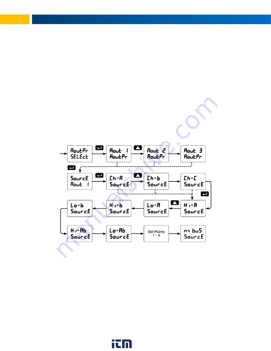
Analog Output Programming (

AoutPr

The 

Analog Output Programming

 menu is used to program the behavior of the 4-20 mA output. The 

following parameters and functions are programmed in this menu: 

1.  Source: Source for generating the 4-20 mA output (e.g. PV) 

2.  Overrange: Analog output value with display in overrange condition 

3.  Underrange: Analog output value with display in underrange condition 

4.  Break: Analog output value when loop break is detected 

5.  Max: Maximum analog output value allowed regardless of input 

6.  Min: Minimum analog output value allowed regardless of input 

7.  Calibrate: Calibrate the internal 4-20 mA source reference used to scale the 4-20 mA output 

Analog Output Source 

The analog output source can be based on either of the input channels (Ch-A, Ch-B), the math channel 

(Ch-C), maximum stored value of either input channel (Hi-A, Hi-B), minimum stored value of either input 

channel (Lo-A, Lo-B), relay set points, or the Modbus input. 


Analog Output Calibration 

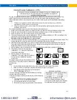
To perform the analog output calibration, it is recommended to use a milliamp meter with a resolution of 

at least 0.1 µA to measure the output current. The values saved internally during this procedure are used 

for scaling the 4-20 mA output in the 

Setup

 menu. 


www.

.com

[email protected]

1.800.561.8187
Summary of Contents for Helios PD2-6060

Page 1: ...A 4 20 mA 0 5 V 1 5 V and 10 V Addition Difference Average Multiplication Division Min Max Weighted Average Ratio Concentration More Input Power Options Include 85 265 VAC or 12 24 VDC Isolated 24 VDC Transmitter Power Supply 32 Point Square Root or Exponential Linearization Multi Pump Alternation Control 2 or 4 Relays Isolated 4 20 mA Output Options Onboard USB RS 485 Serial Communication Options...

Page 2: ... injury or property loss Anyone using this product for such applications does so at their own risk Precision Digital Corporation shall not be held liable for damages resulting from such improper use Limited Warranty Precision Digital Corporation warrants this product against defects in material or workmanship for the specified period under Specifications from the date of shipment from the factory ...

Page 3: ...ay Operation relay 33 Setting the Relay Assignment asSign 34 Setting the Relay Action 34 Programming Set and Reset Points 34 Setting Fail Safe Operation 35 Programming Time Delay 35 Relay Action for Loss of 4 20 mA Input Loop Break 35 Relay and Alarm Operation Diagrams 35 High Alarm Operation Set Reset 35 Low Alarm Operation Set Reset 35 High Alarm with Fail Safe Operation Set Reset 36 Low Alarm w...

Page 4: ...r Digital Input 40 Introduction The Helios PD2 6060 is a multi purpose easy to use large display dual input process meter ideal for level flow rate temperature or pressure transmitter applications It features large 1 8 inch superluminous LED digits which can be read from up to 100 feet away It is housed in a water resistant field mountable NEMA 4X IP65 rated enclosure for convenient indoor or outd...

Page 5: ...ay also be set to show engineering units or be off with no display Programming Methods Four programming buttons digital inputs PC and MeterView Pro software or Modbus registers Noise Filter Programmable from 2 to 199 0 will disable filter Filter Bypass Programmable from 0 1 to 99 9 of calibrated span Recalibration All ranges are calibrated at the factory Recalibration is recommended at least every...

Page 6: ...rift 0 005 of calibrated span C max from 0 to 65 C ambient 0 01 of calibrated span C max from 40 to 0 C ambient Signal Input Conditioning Linear square root programmable exponent or round horizontal tank volume calculation Math Functions Name Function Setting Addition A B P F Sunm Difference A B P F diF Absolute diff Abs A B P F diFAbS Average A B 2 P F AvG Multiplication A B P F nmulti Division A...

Page 7: ...or grand total channel C max or min for channel A or B highest or lowest max or min of A and B set points 1 4 Modbus input or manual control mode Scaling Range 1 000 to 23 000 mA for any display range Calibration Factory calibrated 4 000 to 20 000 4 20 mA output Analog Out 23 000 mA maximum for all parameters Programming Overrange underrange max min and break Accuracy 0 1 of span 0 004 mA Temperat...

Page 8: ...isted USA Canada UL 508 Industrial Control Equipment United States C22 2 No 142 Canadian National Standard UL File Number E160849 Front Panel UL Type 4X NEMA 4X IP65 Low Voltage Directive EN 61010 1 2010 Safety requirements for measurement control and laboratory use www com information itm com 1 800 561 8187 ...

Page 9: ... through the knockout holes located on the bottom of the meter There are a total of four pre drilled conduit entry holes located at the bottom of the meter If the need to drill additional holes arises make sure you will have the clearance necessary for conduit mounting hardware Do not disconnect the RJ45 connector found on the right side of the meter wiring board Doing so will disable the onboard ...

Page 10: ... right on the wall 2 Using a drill bit slightly smaller than the girth of the mounting screws pre drill holes at the mounting locations previously marked 3 Insert mounting screws into the four mounting holes and screw them into the pre drilled holes Do not overtighten the mounting screws as it is possible that the enclosure could crack and become damaged Figure 1 Meter Mounting Holes Mounting Dime...

Page 11: ... instructions 1 Secure the mounting plates to the top and bottom for vertical pipes or left and right for horizontal pipes of the reverse side of the meter enclosure using the provided fasteners Do not overtighten the fasteners as it could cause damage to the enclosure 2 Using the provided nuts and U bolts secure the mounting plates to the pipe enough torque such that the meter cannot be moved up ...

Page 12: ... the center of the connections board see diagram below 4 Flip this switch into the appropriate position for the required transmitter excitation Figure 6 Transmitter Supply Voltage Selection Connections All connections are made to screw terminal connectors located under the front door panel Remove the single securing screw in order to access the wiring terminals Caution Use copper wire with 60 C or...

Page 13: ... located to the left of the power terminal block Doing so will disable the onboard digital I O RS 485 serial communications and M Link functionality Figure 7 Connector Labeling for Fully Loaded PD2 6060 Power Connections Power connections are made to a two terminal connector labeled POWER on Figure 7 on page 13 The meter will operate regardless of DC polarity connection The and symbols are only a ...

Page 14: ...set up for current and voltage inputs Setup and programming is performed through the front panel buttons Figure 9 Transmitters Powered by Internal Supply Figure 10 Transmitter Powered by Ext Supply or Self Powered The current input is protected against current overload by a resettable fuse The display may or may not show a fault condition depending on the nature of the overload The fuse limits the...

Page 15: ... obtained with resistor capacitor RC networks assembled by the user or purchased as complete assemblies Refer to the following circuits for RC network assembly and installation Figure 13 AC and DC Loads Protection Choose R and C as follows R 0 5 to 1 Ω for each volt across the contacts C 0 5 to 1 µF for each amp through closed contacts Notes 1 Use capacitors rated for 250 VAC 2 RC networks may aff...

Page 16: ...network Figure 16 shows the connection of several meters to a PC using a PDA7485 RS 232 to RS 422 485 converter in an RS 485 network When using more than one meter in a multi drop mode each meter must be provided with its own unique address The meter address Slave ID may be programmed between 1 and 247 The transmit delay may be set between 0 and 199 ms The parity can be set to even odd or none wit...

Page 17: ...ion Connections Figure 17 details the wiring connections from the RS 485 connector to an RS 422 485 serial converter such as the PDA7485 or PDA8485 for a four wire network Three Wire Connection In order to wire the 5 pins for use as a 3 wire half duplex RS 485 connection it is necessary to create a jumper connection between DI DO and DI DO as shown below Figure 18 Three Wire RS485 Connection RS485...

Page 18: ...onnector block and the 5 VDC block Digital output connections are made by wiring from the appropriate digital output block to the grounding terminal block Figure 19 Digital Input and Output Connections F4 Digital Input Connections Digital input F4 is also available on the meter This digital input is connected with a normally open contact across F4 and COM or with an active low signal applied to F4...

Page 19: ...by configuring the relay and relative digital input s see page 42 In one example dry interlock contacts are connected in series to one digital input which will be used to force on energize the assigned interlock power relay when all interlock contacts are closed safe The interlock relay front panel LED flashes when locked out The interlock relay would be wired in series with the load N O contact S...

Page 20: ...n the input selection The calibration equipment is certified to NIST standards Overview There are no jumpers to set for the meter input selection Setup and programming are done through the programming buttons located under the front door panel After power and input signal connections have been completed and verified apply power to the meter www com information itm com 1 800 561 8187 ...

Page 21: ...r F3 1 4 Flashing Relay interlock switch open Note F4 F8 are digital inputs Note LEDs for relays in manual mode flash with the M LED every 10 seconds M flashing by itself indicates Aout manual control is used Press the Menu button to enter or exit the Programming Mode at any time Press the Right arrow button to move to the next digit during digit or decimal point programming Press or hold the Up a...

Page 22: ...ick on the drive labeled MAINSTAL 3 Double click on the file named MAStart The program will open a few windows and install two programs on your computer Simply follow the onscreen instructions until you see one of the dialogs below If you receive a User Account Control warning click Yes 4 If there is an update available click the Update button to install the new version Otherwise click Configure t...

Page 23: ...Inp 2 Input 2 Calibrate input 2 signal or program input 2 value up to 32 points Dis 2 Display 2 Program display 2 value up to 32 points Display Parameter Action Setting Description Error Error Error calibration not successful check signal or programmed value dsplay Display Enter the Display menu Line 1 Display Line 1 Press Enter to assign the display line 1 parameter default PV Line 2 Display Line...

Page 24: ... Modbus Asign1 Assign 1 Relay 1 assignment Ch A Channel A Assign relay to channel A or B C m bus Modbus Assign relay to Modbus register RLY 1 Relay 1 Relay 1 setup Act 1 Action 1 Set relay 1 action Display Parameter Action Setting Description Auto Automatic Set relay for automatic reset A nman Auto manual Set relay for automatic manual reset any time LatCH Latching Set relay for latching operation...

Page 25: ... 000 mA reset Reset Press Enter to access the Reset menu Display Parameter Action Setting Description Rst Hi Reset high Press Enter to reset max display Rst Lo Reset low Press Enter to reset min display Rst HL Reset high low Press Enter to reset max min displays Rst tr Reset tare Reset tare Contrl Control Enter Control menu Auto Automatic Press Enter to set meter for automatic operation mAn Manual...

Page 26: ... menu every time a setting is accepted by pressing Enter F3 Setting Numeric Values The numeric values are set using the Right and Up arrow buttons Press Right arrow to select next digit and Up arrow to increment digit value The digit being changed is displayed brighter than the rest Press and hold up arrow to auto increment the display value Press the Enter button at any time to accept a setting o...

Page 27: ...2 Units for A B and C 3 Decimal point position for A B and C 4 Program the meter using the Scale or Calibrate functions 5 Display parameter and intensity 6 Relay assignment and operation 7 4 20 mA analog output scaling Press the Enter button to access any menu or press Up arrow button to scroll through choices Press the Menu button to exit at any time www com information itm com 1 800 561 8187 ...

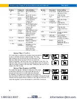
Page 28: ...ustom Tags units Enter the input unit or custom tag that will be displayed if d unit is selected as the little display parameter See the flow chart on page 32 to access the display menu to show the unit or tag on the little display The engineering units or custom legends can be set using the following 7 segment character set Display Character Display Character Display Character Display Character 0...

Page 29: ... A calibrated signal source is not needed to scale the meter Use the Calibrate menu to apply a signal from a calibrator or a flowmeter The Program menu contains the Scale and the Calibrate menus for channels A B The process inputs may be calibrated or scaled to any display value within the range of the meter Note The Scale and Calibrate functions are exclusive of each other The meter uses the last...

Page 30: ...everts to the input prior to the failure during calibration or scaling and to input 1 during internal calibration allowing the appropriate input signal to be applied or programmed The error message might be caused by any of the following conditions 1 Input signal is not connected to the proper terminals or it is connected backwards 2 Wrong signal selection in Setup menu 3 Minimum input span requir...

Page 31: ...least 15 minutes before performing calibration to ensure specified accuracy The meter can be calibrated to display the process variable in engineering units by applying the appropriate input signal and following the calibration procedure The use of a calibrated signal source is strongly recommended to calibrate the meter Calibrating the Meter for Channel A CAL A Calibrating the Meter for Channel B...

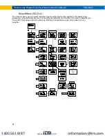
Page 32: ...its 8 Channel gross value no tare or toggle net tare and gross values 9 Modbus input 10 Off no display 11 Engineering units or custom legends Display Intensity The meter has eight display intensity levels to give the best performance under various lighting conditions Select intensity 8 for outdoor applications The default intensity setting is 8 After setting up the input and display press the Menu...

Page 33: ...matic reset only non latching b Automatic manual reset at any time non latching c Latching manual reset only d Latching with Clear manual reset only after alarm condition has cleared e Pump alternation control automatic reset only f Sampling the relay is activated for a user specified time g Off relay state controlled by Interlock feature 3 Set point 4 Reset point 5 Fail safe operation a On enable...

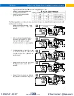
Page 34: ...set only 6 Sampling the relay is activated for a user specified time 7 Off relay state controlled by Interlock feature The following graphic shows relay 1 action setup relay 2 8 are set up in a similar fashion Programming Set and Reset Points High alarm indication program set point above reset point Low alarm indication program set point below reset point The deadband is determined by the differen...

Page 35: ...k The loop break feature is associated with the 4 20 mA input Each relay may be programmed to go to one of the following conditions when the meter detects the loss of the input signal i e 0 005 mA 1 Turn On Go to alarm condition 2 Turn Off Go to non alarm condition 3 Ignore Processed as a low signal condition Note This is not a true loop break condition if the signal drops below 0 005 mA it is int...

Page 36: ...y coil is energized in non alarm condition In case of power failure relay will go to alarm state Low Alarm with Fail Safe Operation Set Reset Note Relay coil is energized in non alarm condition In case of power failure relay will go to alarm state Pump Alternation Control Operation www com information itm com 1 800 561 8187 ...

Page 37: ... 2 Turn Off Go to non alarm condition 3 Ignore Processed as a low signal condition Time Delay Operation The following graphs show the operation of the time delay function When the signal crosses the set point the On time delay timer starts and the relay trips when the time delay has elapsed If the signal drops below the set point high alarm before the time delay has elapsed the On time delay timer...

Page 38: ...nel LEDs The LEDs on the front panel provide status indication for the following The meter is supplied with four alarm points that include front panel LEDs to indicate alarm conditions This standard feature is particularly useful for alarm applications that require visual only indication The LEDs are controlled by the set and reset points programmed by the user When the display reaches a set point...

Page 39: ... In this application the meter is set up for manual reset at any time Acknowledging the alarm even if the alarm condition is still present resets the relay and turns off the LED Latching Relay Lt Clr In this application the meter is set up for manual reset only after the signal passes the reset point alarm condition has cleared Acknowledging the alarm while it is still present has no effect on eit...

Page 40: ...rnation Using Relays 1 2 1 Relays 1 and 2 are set up for pump alternation 2 Relays 3 and 4 are set up for low and high alarm indication Pump Alternation Operation 1 Pump 1 turns on when level reaches 30 000 when level drops below 10 000 pump 1 turns off 2 The next time level reaches 30 000 pump 2 turns on when level drops below 10 000 pump 2 turns off 3 If the level doesn t reach 35 000 pump 1 and...

Page 41: ...eature activated the next time the level reaches 6000 gallons relay 3 transfers and starts the backup pump 3 If the backup pump is not able to keep up and the level reaches 7000 gallons relay 4 transfers and starts the main pump as well 4 Relay 2 trips the High Level Alarm at 7500 gallons and resets at 6900 gallons 5 Relay 1 trips the Low Level Alarm at 495 gallons and resets at 750 gallons Set an...

Page 42: ...nding digital input dI 1 to dI 4 terminal Interlock Relay Operation Example Relays 1 2 are configured to energize their front panel LEDs are off when SW1 SW2 switches above are closed If the contacts to these digital inputs are opened the corresponding front panel LEDs flash indicating this condition The processes being controlled by the interlock relay will stop and will re start only after the i...

Page 43: ...to program numeric values see Setting Numeric Values page 26 Reset Menu reset The Reset menu is used to reset the maximum or minimum reading peak or valley reached by the process both may be reset at the same time by selecting reset high low rst HL The tare value used to zero the display may be reset by selecting reset tare rst tr Control Menu Contrl The Control menu is used to control the 4 20 mA...

Page 44: ...ital inputs and editing set reset points Pass 3 Restricts all programming function keys and digital inputs Protecting or Locking the Meter Enter the Password menu and program a six digit password For instructions on how to program numeric values see Setting Numeric Values page 26 Record the password for future reference If appropriate it may be recorded in the space provided Model Serial Number Pa...

Page 45: ...he Password menu and enter the correct password twice as shown below The meter is now unprotected until a new password is entered If the correct six digit password is entered the meter displays the message unLoc unlocked and the protection is disabled until a new password is programmed If the password entered is incorrect the meter displays the message Locd Locked for about two seconds and then it...

Page 46: ...lter bypass value for channel B Round Round Set the rounding value for display variables seriAl Serial Set serial communication parameters SlaveId Slave ID Set slave ID or meter address baud Baud rate Select baud rate Tr dLY Transmit delay Set transmit delay for serial communication Display Parameter Action Setting Parity Parity Select parity Even Odd or None with 1 or 2 stop bits t byt Time byte ...

Page 47: ...tion constant used in channel C math calculations P Display Parameter Action Setting factor Factor Multiplication constant used in channel C math calculations F CutofF Cutoff Set low flow cutoff Ch A Channel A Set low flow cutoff for Channel A Ch b Channel B Set low flow cutoff for Channel B AoutPr Analog output programmi ng Program analog output parameters AOut 1 Analog output 1 Program analog ou...

Page 48: ...stics Display parameter settings LED t LED test Test all LEDs Info Information Display software and S N information Erase Erase Delete the MeterView Pro installation files from the meter Noise Filter filter The noise filter is available for unusually noisy signals that cause an unstable process variable display The noise filter averages the input signal over a certain period The filter level deter...

Page 49: ...d instructions are provided with each optional serial communications adapter Note Refer to the Modbus Register Tables for details When using more than one meter in a multi drop mode each meter must be provided with its own unique address The meter address Slave ID may be programmed between 1 and 247 The transmit delay may be set between 0 and 199 ms The parity can be set to even odd or none with 1...

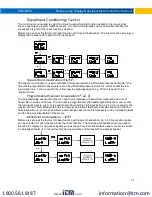
Page 50: ...lect the signal input conditioning function applied to the inputs linear square root programmable exponent or round horizontal tank math function for A B constants low flow cutoff and analog output programming Multi point linearization is part of the linear function selection www com information itm com 1 800 561 8187 ...

Page 51: ...rammable Exponent Linearization Prog E The programmable exponent function is used to calculate open channel flow measured with a level transmitter in weirs and flumes The flow rate is proportional to the head height Scale the meter so that the low input signal e g 4 mA is equal to zero flow and the high input signal e g 20 mA is equal to the maximum flow This method works well for all weirs and fl...

Page 52: ...in Note After Scale is displayed continue pressing the Enter button until the meter completes the scaling of the input and display values Changing the Volume from Gallons to Liters In the above graphic entering the 48 for the diameter and 120 for the length of the round horizontal tank the meter automatically calculates that the volume of the tank is 940 02 gallons 1 Convert gallons to liters 2 1 ...

Page 53: ...ivide Divide Channel C A B P F Hi ab Max of A or B C High value of channel A or B P F Lo ab Min of A or B C Low value of channel A or B P F Drauw Draw Channel C A B 1 F uwAvg Weighted avg Channel C B A F A ratio Ratio Channel C A B F Ratio2 Ratio 2 C B A A P F Concen Concentration Channel C A A B F Math Constants Const The Math Constants menu is used to set the constants used in channel C math The...

Page 54: ...ge condition 3 Underrange Analog output value with display in underrange condition 4 Break Analog output value when loop break is detected 5 Max Maximum analog output value allowed regardless of input 6 Min Minimum analog output value allowed regardless of input 7 Calibrate Calibrate the internal 4 20 mA source reference used to scale the 4 20 mA output Analog Output Source The analog output sourc...

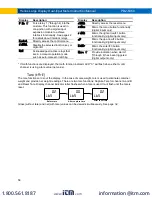
Page 55: ...D flashes same rate as M Rst tr Reset captured tare and resume normal operation for both channels A B relay Directly access the relay menu Set 1 Directly access the set point menu for relay 1 through 8 Rly d Disable all relays until a button assigned to enable relays Rly E is pressed Rly E Enable all relays to function as they have been programmed O Hold Hold current relay states and analog output...

Page 56: ...up Mimic the up arrow F2 button functionality digital inputs only Enter Mimic the enter F3 button functionality digital inputs only Alnm 1 Provide indication when alarm 1 through 8 has been triggered digital outputs only If math functions are displayed the math function indicator LED C will flash when either A or B channel is using a tare value net value Tare tare The tare function zero s out the ...

Page 57: ...t signal and press Enter The display flashes for a moment while the meter is accepting the low input signal 6 After the display stops flashing a number is displayed with the leftmost digit brighter than the rest The bright digit is the active digit that can be changed by pressing the Up arrow button Press the Right arrow button to move to the next digit 7 Set the display value to correspond to the...

Page 58: ...ased on any input or math channel Button Operation Button Symbol Description Press to enter or exit Programming Mode view settings or exit max min readings Press to reset max min readings or other parameter function assigned through the User menu Press to display max min readings or other parameter function assigned through the User menu Press to acknowledge relays or other parameters function ass...

Page 59: ...e reset to actual values 4 Press Menu to exit max min display reading Troubleshooting Due to the many features and functions of the meter it s possible that the setup of the meter does not agree with what an operator expects to see If the meter is not working as expected refer to the Diagnostics menu and recommendations below Diagnostics Menu diag The Diagnostics menu is located in the Advanced Fe...

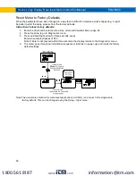
Page 60: ...tures Menu page 46 4 Press Up arrow to go to Diagnostics menu 5 Press and hold Right arrow for three seconds press Enter when display flashes reset Note If Enter is not pressed within three seconds the display returns to the Diagnostics menu 6 The meter goes through an initialization sequence similar as on power up and loads the factory default settings Note The dual scale selection for some level...

Page 61: ...a 0 000 disabled Parameter Display Default Setting Cutoff value channel B Ch b 0 000 disabled Display assignment Dsplay Display Line 1 D Ch A Channel A Display Line 2 d Ch B Channel B Display intensity d Inty 8 Relay 1 assignment Ch A Channel A Relay 1 action Act 1 Automatic Relay 1 set point Set 1 1 000 Relay 1 reset point RSt 1 0 500 Relay 2 assignment Ch A Channel A Relay 2 action Act 2 Automat...

Page 62: ...e baud 9600 Transmit delay Tr dly 50 ms Parity Parity Even Byte to byte timeout t byt 010 0 1 sec Parameter Display Default Setting F1 function key F1 Reset max min F2 function key F2 Upper Max Min F3 function key F3 Acknowledge relays F4 function digital input F4 Acknowledge relays Digital input 1 DI 1 Menu Digital input 2 DI 2 Right arrow Digital input 3 DI 3 Up arrow Digital input 4 DI 4 Enter ...

Page 63: ...splay does not respond to input changes reading a fixed number Check Display assignment it might be displaying max min or set point Display alternates between Hi and a number Lo and a number Press Menu to exit max min display readings Relay operation is reversed Check Fail safe in Setup menu Wiring of relay contacts Relay and status LED do not respond to signal Check Relay action in Setup menu Set...

Reviews: