


P
RO
V
U
™ PD6001 Analog Input Feet & Inches Meter
Instruction Manual
17
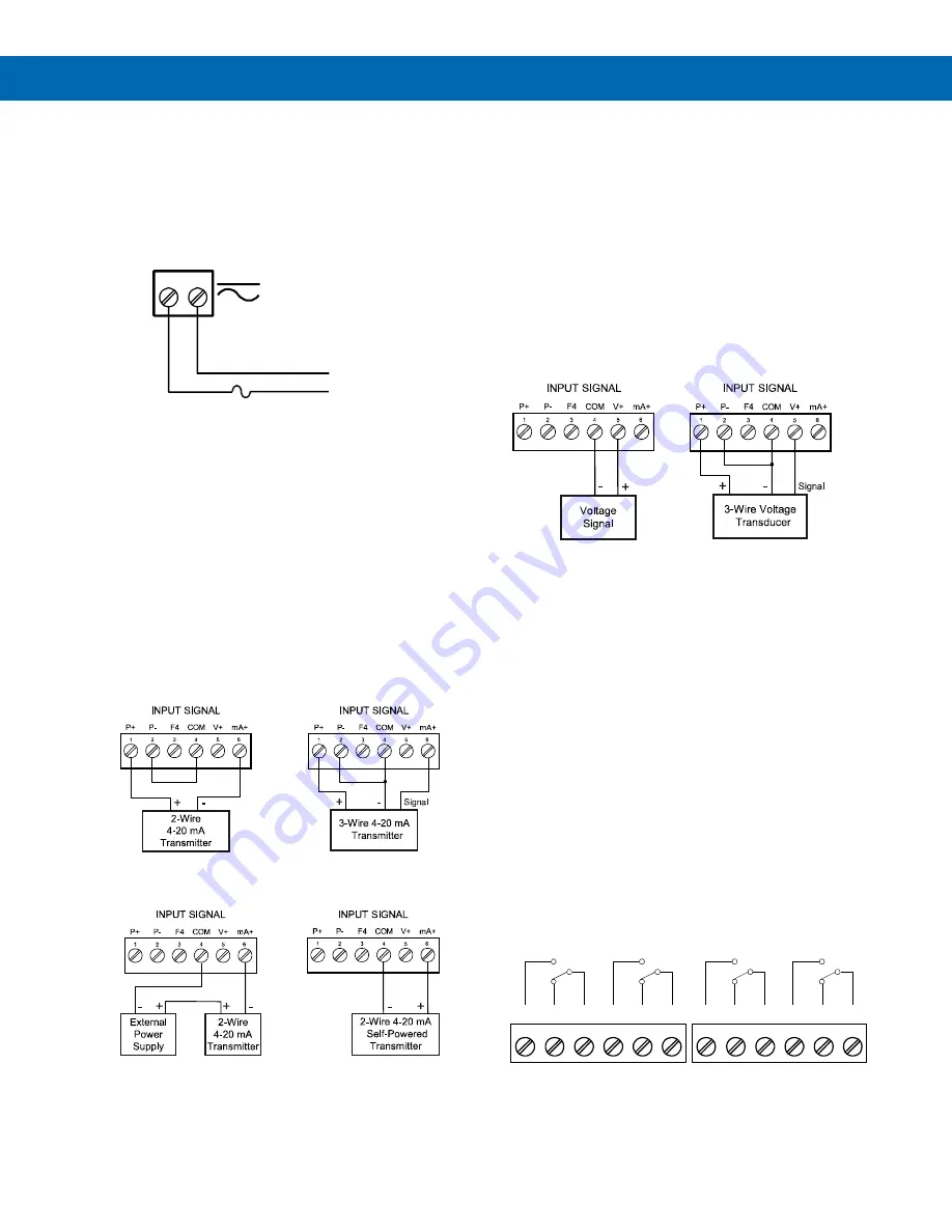
Power Connections
Power connections are made to a two-terminal
connector labeled POWER. The meter will operate
regardless of DC polarity connection. The + and -
symbols are only a suggested wiring convention. There
are separate meters for AC and DC power. See
Figure 12. Power Connections
Signal Connections
Signal connections are made to a six-terminal
connector labeled SIGNAL. The COM (common)
terminal is the return for the
4-20 mA and the
10 V input signals.
Current (mA) Connections
The following figures show examples of current
connections.
There are no switches or jumpers to set up for current
inputs. Setup and programming is performed through
the front panel buttons or MeterView Pro software.
Figure 13. Transmitter Powered by Internal Supply
Figure 14. Transmitter Powered by External
Supply or Self-Powered
The current input is protected against current
overload by an internal resettable fuse. The display
may or may not show a fault condition depending on
the nature of the overload.
The fuse limits the current to a safe level when it
detects a fault condition, and automatically resets
itself when the fault condition is removed.
Voltage (V) Connections
The following figures show examples of voltage
connections.
There are no switches or jumpers to set up for voltage
inputs. Setup and programming is performed through
the front panel buttons or MeterView Pro software.
Figure 15. Voltage Input Connections
The meter is capable of accepting any voltage from -
10 VDC to +10 VDC.
Modbus RTU Serial
Communications
Serial communications connection is made to an
RJ45 connector labeled M-LINK. For interfacing to the
P
RO
V
U
, use the PDA1232 for RS-232 or the PDA1485
for RS-485. The same port is used for interfacing with
all expansion modules (
e.g.
external relays, digital
I/O).
Relay Connections
Relay connections are made to two six-terminal
connectors labeled RELAY1
– RELAY4. Each relay’s
C terminal is common only to the normally open (NO)
and normally closed (NC) contacts of the
corresponding relay. The relays’ C terminals should
not be confused with the COM (common) terminal of
the INPUT SIGNAL connector.
Figure 16. Relay Connections
AC or DC
POWER
Required External Fuse:
5 A max, 250 V Slow Blow
POWER
+
-
C
NO
NO
NC
NC
C
RELAY4
RELAY3
4
3
6
5
2
1
C
NO
NO
NC
NC
C
RELAY2
RELAY1
4
3
6
5
2
1


