Helios PD2-6080/PD2-6081 Modbus
®
Scanners
Instruction Manual
19
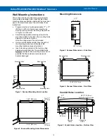
Power Connections
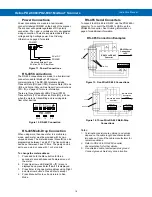
Power connections are made to a two-terminal
connector labeled POWER on the back of the scanner.
The scanner will operate regardless of DC polarity
connection. The + and - symbols are only a suggested
wiring convention. There are separate models for low
voltage and high voltage power. See
on page
Figure 11. Power Connections
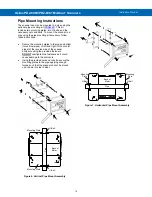
RS-485 Connections
The RS-485 connections are made to a five terminal
connector used for Modbus
®
RTU serial
communications. The RS-485 terminals include
Transmit Data (DO) and (/DO), Receive Data (DI) and
(/DI), and Signal Ground. See
) on page
There are three diagnostic LEDs: Power (PWR)
Transmit Data (TX), and Receive Data (RX) to show
when the meter is transmitting and receiving data
from other devices.
Figure 12. RS-485 Connection
RS-485 Multi-Drop Connection
When using more than one meter in a multi-drop
mode, each meter must be provided with its own
unique address. The meter address (Slave ID) can be
programmed between 1 and 247. The transmit delay
can be set between 0 and 199 ms. The parity can be
set to even, odd, or none with 1 or 2 stop bits.
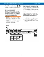
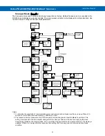
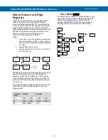
To change the meter address:
1. Press and hold the Menu button for three
seconds to access Advanced Features menu of
the meter.
2. Press Up arrow until Serial (
SEriaL
) menu is
displayed and press Enter,
Addres
is displayed.
3. Press Enter to change meter address using Right
and Up arrow buttons. Press Enter to accept.
4. Press Menu button to exit and return to Run
Mode.
RS-485 Serial Converters
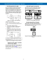
To convert the RS-485 to RS-232, use the PDA7485-I
converter. To convert the RS-485 to USB, use the
PDA8485-I converter. See
page
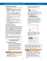
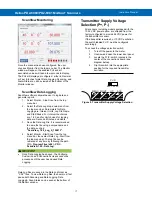
RS-485 Connection Examples
Figure 13. Five-Wire RS-485 Connections
Figure 14. Three-Wire RS-485 Multi-Drop
Connections
Notes:
1. Termination resistors are optional, and values
depend on the cable length and characteristic
impedance. Consult the cable manufacturer for
recommendations.
2. Refer to RS-232 to RS-485 Converter
documentation for further details.
3.
Use shielded cable, twisted-pair plus ground.
Connect ground shield only at one location
AC or DC
POWER
Required External Fuse:
5 A max, 250 V Slow Blow
POWER
+
-
RS-485
PWR
TX
RX
DI
DI DO DO
__ __
Shield
RS-232 Serial
Connection
to PC
R
R
Twisted-Pair
R
DI
DI DO DO
__ __
RS-232 to RS-485
Converter
DI
DI
DO
DO
R
Shield
Twisted-Pair
R
Meter #1
DI
DI DO DO
__ __
DI
DI DO DO
__ __
Last Meter
RS-232 Serial
Connection
to PC
R
RS-232 to RS-485
Converter
DI
DI
DO
DO

