37
Follow the steps below for Tuning the controller manually.
1. Set the value of the SP at which the Manual Tuning is desired or slightly below if the overshoots caused by the oscillations
near the operating value are damaging.
2. Cut-off Integral and Derivative actions by setting the parameter values to 0.
3. Set the ‘Motor Run Time’ to the time taken to travel the valve from its fully close position (one physical end) to fully open
position (other physical end) or vice-a-versa.
4. Set the ‘Valve Inertia Time’ and ‘Valve Backlash Time’ (if required) to the appropriate values.
5. Set the ‘Minimum ON Time’ to execute the minimum pulse duration (Forward or Reverse) to drive the motor to initiate valve
movement.
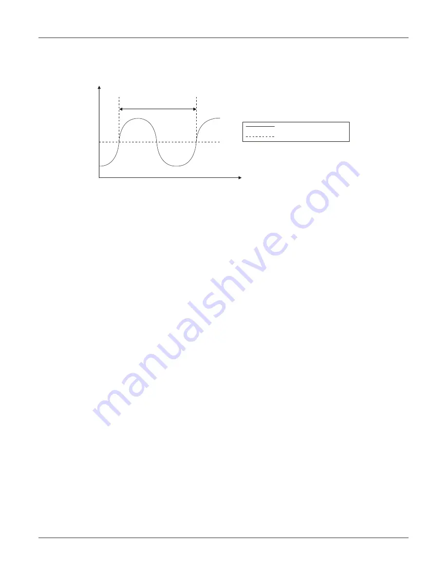
6. Reduce ‘Proportional Band’ value until the PV oscillates. Since the controller is operating in proportion-only mode, the PV
oscillations shall occur with an offset error. Ignore this error and measure the period of oscillation as T, as shown in the
Figure 10.2 above.
7. Keep increasing the ‘Proportional Band’ value in small steps until the PV just stabilizes. Allow enough time between the
steps for the process to response to the changes made. Note the value of the ‘Proportional Band’ at which the oscillations
just cease (stop), as P.
8. Compute the ‘Proportional Band’, ‘Integral Time’ and ‘Derivative Time’ from the measured values of P and T as per the
following Table 10.1.
9. Set these values for the controller parameters ‘Proportional Band’, ‘Integral Time’ and ‘Derivative Time’ in PAGE-10
parameter list.
Figure 10.2
T
Process Value
(PV)
Setpoint
(SP)
User Manual
neuro 104


