background image

10

Step 6:

 Insert the slotted bushing with the blade into the automation axis.

To complete the installation, screw fairing operator before its operate.

BOARD COMMAND:

Check the label attached to the product 

(according to the model on the side) which is the 

board part of the operator. After doing this, refer 

to the PBX manual that is available for download 

at www.ppa.com and make all connections and 

configurations

Lot:

Code:

Model:

Reduction:

Technology:

Voltage:

Board:

Size:

Assembly:

Fairing:

Gear:

Illustr

ativ

e pic

tur

e.

Summary of Contents for TORSION

Page 1: ......

Page 2: ......

Page 3: ...Important safety instructions 3 Technical specifications 4 Tools required for installation 5 Electrical installation 5 Caring for the gate before operator 6 Installing and fixing the operator 6 Mainte...

Page 4: ...el Do not connect the power grid until installation maintenance is complete Make the electrical connections of the board always turning off the power grid Do not change the voltage jumper The voltage...

Page 5: ...L FREQUENCY 50 Hz RATED POWER 300 W MOTOR ROTATION 4600 rpm NOMINAL CHAIN 2 5 A LINEAR SPEED 11m min REDUCTION 1 800 MANEUVERS 60 cycles hours DEGREE OF PROTECTION IPX 0 RAIL ALUMINIUM MEASURES FOR LE...

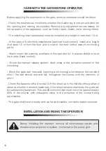
Page 6: ...the electrical distribution box and the total shutdown device 3 4 diameter conduit between the total shut off device and the operator connection point 1 2 diameter conduits for external and optional p...

Page 7: ...sible or near the button fixed control Check the manual release system fixed close to the actuation element of the unlocking Move the gate leaf manually opening and closing and observe the required ef...

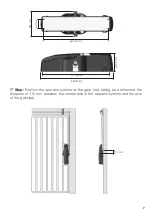
Page 8: ...mm 477 36 mm 66 mm 181 mm 132 5 mm 1 Step Position the operator system on the gate leaf taking as a reference the distance of 110 mm between the central axis of the operator system and the axis of the...

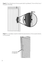
Page 9: ...at the tip of the operator shaft is positioned 10 mm off the line of the gate connecting Step 3 It is necessary to weld or fasten the base structure of the operator directly to the gate leaf FIXATION...

Page 10: ...ase of the gate with screws Step 5 Position the sheath assembly support on the top of the gate and install it through the screw obeying the distance of 110 mm between the end of the gate leaf and the...

Page 11: ...COMMAND Check the label attached to the product according to the model on the side which is the board part of the operator After doing this refer to the PBX manual that is available for download at w...

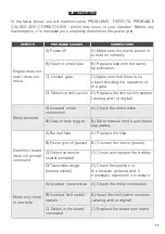
Page 12: ...Replace the limit switch system analog and or digital Motor blocked A Inverted motor connection A Check the motor wires B Gate or lock trigger B Set to manual mode and check separately Electronic boa...

Reviews: