background image

6

CARE WITH THE GATE BEFORE OPERATOR

Before applying the automation to the gate, some procedures should be taken:

- Check the mechanical conditions, whether the balancing is correct and whether 

the opening and closing are suitable. Remove any equipment not necessary for 

the operation of the apparatus, such as locks, ropes, chains, tools, among others 

- The unlocking (manual release) must be installed at a height of less than 1,8 m;

- In the case of buttonhole installations (optional fixed control), install at a height 

of at least 1.5 m from the floor and in view of the door, further away from moving 

parts;

- Attach crush risk warning, available in the operator kit, in places visible or near 

the button (fixed control);

- Check the manual release system, fixed close to the actuation element of the 

unlocking;

- Move the gate leaf manually (opening and closing) and observe the required 

effort. The leaf should rise and fall, throughout the course, with the minimum of 

effort;

- Check the balance of the door leaf. Lift the sheet up to the middle of the path and 

observe whether it remains stationary. If the sheet remains stationary, the gate will 

be satisfactorily balanced. This equilibrium condition must occur for approximately 

80% of the course, with imbalance close to the extremes of the course being 

permissible.

- The gate shall have a sturdy and, as far as possible, non-deformable structure.

INSTALLATION AND FIXING THE OPERATOR

Before installing the operator, remove all unnecessary cables and 

disable any equipment or system connected to the power grid.

Summary of Contents for TORSION

Page 1: ......

Page 2: ......

Page 3: ...Important safety instructions 3 Technical specifications 4 Tools required for installation 5 Electrical installation 5 Caring for the gate before operator 6 Installing and fixing the operator 6 Mainte...

Page 4: ...el Do not connect the power grid until installation maintenance is complete Make the electrical connections of the board always turning off the power grid Do not change the voltage jumper The voltage...

Page 5: ...L FREQUENCY 50 Hz RATED POWER 300 W MOTOR ROTATION 4600 rpm NOMINAL CHAIN 2 5 A LINEAR SPEED 11m min REDUCTION 1 800 MANEUVERS 60 cycles hours DEGREE OF PROTECTION IPX 0 RAIL ALUMINIUM MEASURES FOR LE...

Page 6: ...the electrical distribution box and the total shutdown device 3 4 diameter conduit between the total shut off device and the operator connection point 1 2 diameter conduits for external and optional p...

Page 7: ...sible or near the button fixed control Check the manual release system fixed close to the actuation element of the unlocking Move the gate leaf manually opening and closing and observe the required ef...

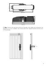
Page 8: ...mm 477 36 mm 66 mm 181 mm 132 5 mm 1 Step Position the operator system on the gate leaf taking as a reference the distance of 110 mm between the central axis of the operator system and the axis of the...

Page 9: ...at the tip of the operator shaft is positioned 10 mm off the line of the gate connecting Step 3 It is necessary to weld or fasten the base structure of the operator directly to the gate leaf FIXATION...

Page 10: ...ase of the gate with screws Step 5 Position the sheath assembly support on the top of the gate and install it through the screw obeying the distance of 110 mm between the end of the gate leaf and the...

Page 11: ...COMMAND Check the label attached to the product according to the model on the side which is the board part of the operator After doing this refer to the PBX manual that is available for download at w...

Page 12: ...Replace the limit switch system analog and or digital Motor blocked A Inverted motor connection A Check the motor wires B Gate or lock trigger B Set to manual mode and check separately Electronic boa...

Reviews: