background image


IT 

1)


Press the “OFF” key twice and each time should be lasted for more than 0.5s. Then, the UPS will 

enter into bypass mode or no output mode without output.   

2)


Turn off the output breaker of this unit, and then turn off the input breaker of this unit. 

3)


After it shuts down, you can turn off the battery breaker (for long-run model) and remove the 

parallel and share current cables. And then remove the unit from the parallel system. 

Second method: 
1)


If the bypass is abnormal, you can not remove the UPS without interruption. You must cut off the 

load and shut down the system first. 

2)


Make sure the bypass setting is enabled in each UPS and then turn off the running system. All UPSs 

will transfer to Bypass mode. Remove all the maintenance bypass covers and set the maintenance 

switches from “UPS” to “BPS”. Turn off all the input breakers and battery breakers in parallel system.   

3)


Turn off the output breaker and remove the parallel cable and share current cable of the UPS which 

you want to remove. Then, remove it from parallel system. 

4)


Turn on the input breaker of the remaining UPS and the system will transfer to Bypass mode.


Set 

the maintenance switches from “BPS” to “UPS and put the maintenance bypass covers back.   

5)


Turn on the remaining UPS according to the previous section. 


Warning: 

(Only for the parallel system) 

● Before turning on the parallel system to activate inverter, make sure that all 

unit’s maintenance switch 

at the same position. 

● When 

parallel system is turned on to work through inverter, please do not operate the maintenance 

switch of any unit. 


3-6. LCD-Display Index der Formulierungen 

Abkürzung 

Anzeige 

Bedeutung 

ENA 


Aktivieren


DIS 


Deaktivieren


ATO 


Auto 

BAT 


Akku 

NCF 


Normal Modus 

CF 


Konverter-Modus 

SUB 


Subtract 

ADD 


Hintufugen 

ON 


An 

OFF 


Aus 

FBD 


Nicht erlaubt 

OPN 


Erlaubt 

RES 


Reserviert 

N.L 


Neutral Leitungsverlust 

CHE 


Prüfen 

Summary of Contents for 10000

Page 1: ...EN Online UPS PowerWalker VFI 10000CP 3 3 PowerWalker VFI 15000CP 3 3 PowerWalker VFI 20000CP 3 3 PowerWalker VFI 30000CP 3 3 Bedienungsanleitung Unterbrechungsfreie Stromversorgung ...

Page 2: ......
Page 3: ... INSTALLATION 5 2 4 UPS INSTALLATION FOR PARALLEL SYSTEM 8 2 5 SOFTWARE INSTALLATION 9 3 OPERATIONS 10 3 1 BUTTON OPERATION 10 3 2 LED INDICATORS AND LCD PANEL 11 3 3 AUDIBLE ALARM ERROR BOOKMARK NOT DEFINED 3 4 SINGLE UPS OPERATION 13 3 5 PARALLEL OPERATION 16 3 6 ABBREVIATION MEANING IN LCD DISPLAY 17 3 7 LCD SETTING 18 3 8 OPERATING MODE STATUS DESCRIPTION 25 3 9 FAULT CODE 31 3 10 WARNING INDI...

Page 4: ...m Sonnenlicht ausgesetzt ist Halten Sie die Ventilationsöffnungen des USV Gehäuses frei 1 3 Installation Schließen Sie keine Geräte an die USV an die diese überlasten könnten Verlegen Sie die Kabel so dass niemand darüber stolpern kann Do not block air vents in the housing of UPS The UPS must be installed in a location with good ventilation Ensure enough space on each side for ventilation UPS has ...

Page 5: ...n Flüssigkeit oder fremder Objekte in die USV Die USV kann von jedermann ohne Erfahrung betreiben werden 1 5 Standard Safety IEC EN 62040 1 EMI Conducted Emission IEC EN 62040 2 Category C3 Radiated Emission IEC EN 62040 2 Category C3 EMS ESD IEC EN 61000 4 2 Level 4 RS IEC EN 61000 4 3 Level 3 EFT IEC EN 61000 4 4 Level 4 SURGE IEC EN 61000 4 5 Level 4 CS IEC EN 61000 4 6 Level 3 Power frequency ...

Page 6: ...rallel Model in the following chapter 2 1 Unpacking and Inspection Unpack the package and check the package contents The shipping package contains One UPS One user manual One monitoring software CD One RS 232 cable option One USB cable One parallel cable only available for parallel model One share current cable only available for parallel model NOTE Before installation please inspect the unit Be s...

Page 7: ...2 2 Hintere Konsolenansicht Diagramm 1 10000 L 15000 L Diagramm 2 30000L Diagramm 3 30000 20000 L Rear Panel Diagramm 3 10000 L 15000 L 20000 L Diagramm 4 30000 L Input Output Terminal Input Output Terminal ...

Page 8: ... must be performed in accordance with the local electric laws regulations and execute the following instructions by professional personnel 1 Make sure the mains wire and breakers in the building are enough for the rated capacity of UPS to avoid the hazards of electric shock or fire NOTE Do not use the wall receptacle as the input power source for the UPS as its rated current is less than the UPS s...

Page 9: ...re for Phase and AWG 6 or thicker wire for Neutral for safety and efficiency NOTE 4 The cable for 30000 30000L should be able to withstand over 63A current It is recommended to use AWG 8 or thicker wire for Phase and AWG 4 or thicker wire for Neutral for safety and efficiency NOTE 5 The selections for color of wires should be followed by the local electrical laws and regulations 5 Remove the termi...

Page 10: ...Make sure a DC breaker or other protection device between UPS and external battery pack is installed If not please install it carefully Switch off the battery breaker before installation NOTE Set the battery pack breaker in OFF position and then install the battery pack Pay highly attention to the rated battery voltage marked on the rear panel If you want to change the numbers of the battery pack ...

Page 11: ...es of each UPS to an output breaker 3 Connect all output breakers to a major output breaker Then this major output breaker will directly connect to the loads 4 Each UPS is connected to an independent battery pack NOTE The parallel system can not use one battery pack Otherwise it will cause system permanent failure 5 Refer to the following wiring diagram Wiring diagram of parallel system for 10000 ...

Page 12: ...IT Wiring diagram of parallel system for 30000 L 2 5 Software Installation For optimal computer system protection install UPS monitoring software to fully configure UPS shutdown ...

Page 13: ...Test Oben Taste Akkutest Drücken Sie die Test Tasten gleichzeitig für 0 5 Sekunden um den Selbsttest aufzurufen währen sich die USV im Netzbetrieb oder Konverter Modus befindet Drücken Sie diese Taste um die nächste Auswahl in den USV Einstellungen anzuzeigen Mute Unten Taste Stummschaltung des Alarms Sobald die USV im Akkubetrieb ist drücken und halten Sie diese Taste für mindesten 0 5 Sekunde um...

Page 14: ... panel to show the UPS working status Modus LED Bypass Line Akkus Fehler UPS An Keine Ausgang Modus Bypassmodus AC Modus Akkumodus Konverter Modus Akku Test ECO Modus Fehler Note means LED is lighting and means LED is faded LCD Panel LCD panel LED indicators ...

Page 15: ...nnung Frequenz oder Akkuspannung an Vac Ausgangsspannung Vdc Akkuspannung Hz Frequenz Last Zeigt die Last in 0 25 26 50 51 75 und 76 100 an Zeigt Überlastung an Zeigt einen Kurzschluss an USV oder angeschlossenen Geräten an Betriebsmodus Zeigt an dass das die USV an das Stromnetz angeschlossen ist Zeigt an dass der Akku einwandfrei funktioniert Zeigt an dass der Bypass einwandfrei funktioniert Zei...

Page 16: ...er UPS operates in Bypass mode and supplies power to the loads via the bypass NOTE When UPS is in Bypass mode the output voltage will directly power from utility after you switch on the input breaker In Bypass mode the load is not protected by UPS To protect your precious devices you should turn on the UPS Refer to next step 2 Press and hold the ON button for 0 5s to turn on the UPS and the buzzer...

Page 17: ...Battery mode operation 1 When the UPS is in Battery mode the buzzer will beep according to different battery capacity If the battery capacity is more than 25 the buzzer will beep once every 4 seconds If the battery voltage drops to the alarm level the buzzer will beep quickly once every sec to remind users that the battery is at low level and the UPS will shut down automatically soon Users could s...

Page 18: ...ult LED illuminates and the buzzer beeps continuously it means that there is a fatal error in the UPS Users can get the fault code from display panel Please check the trouble shooting table in chapter 4 for details 2 Please check the loads wiring ventilation utility battery and so on after the fault occurs Don t try to turn on the UPS again before solving the problems If the problems can t be fixe...

Page 19: ...AC mode a Turn on the line input breaker of each UPS for dual input also turn on bypass input breaker After all UPSs enter to bypass mode measure the output voltage between two UPS for the same phase to make sure the phase sequence is correct If these two voltage differences are near to zero that means all connections are correct Otherwise please check if the wirings are connected correctly b Turn...

Page 20: ...ut breakers and battery breakers in parallel system 3 Turn off the output breaker and remove the parallel cable and share current cable of the UPS which you want to remove Then remove it from parallel system 4 Turn on the input breaker of the remaining UPS and the system will transfer to Bypass mode Set the maintenance switches from BPS to UPS and put the maintenance bypass covers back 5 Turn on t...

Page 21: ...r 3 geben die Einstelloptionen oder Werte für jedes Programm wieder Programs available list for parameter 1 Code Beschreibung Bypass Kein Ausgang Modus AC Modus ECO Modus Konwerter Modus Akkusmodus Akkutest 01 Ausgangsspannung Y 02 Ausgangsfrequenz Y 03 Spannungsbereich für Bypass Y 04 Frequenzbereich für Bypass Y 05 ECO Modus aktivieren deaktivieren Y 06 Spannungsbereich für ECO Modus Y 07 Freque...

Page 22: ...angsspannungseinstellung Interface Einstellung Parameter 3 Ausgangsspannung Bei den Modellen 200 208 220 230 240 VAC können folgende Ausgangsspannung eingestellt werden 200 Ausgangsspannung 200V Wechselstrom 208 Ausgangsspannung 208V Wechselstrom 220 Ausgangsspannung 220V Wechselstrom 230 Ausgangsspannung 230V Wechselstrom 240 Ausgangsspannung 240V Wechselstrom 02 Frequenzumwandler Interface Einst...

Page 23: ...l Output relay board for CVCF application 03 Voltage range for bypass Interface Setting Parameter 2 Set the acceptable low voltage for bypass Setting range is from 110V to 209V and the default value is 110V Parameter 3 Set the acceptable high voltage for bypass Setting range is from 231V to 276V and the default value is 264V 04 Frequency range for bypass Interface Setting Parameter 2 Set the accep...

Page 24: ... UPS will run at Bypass mode depending on bypass enabled disabled setting FBD Bypass not allowed When selected it s not allowed for running in Bypass mode under any situations Parameter 3 ENA Bypass enabled When selected Bypass mode is activated DIS Bypass disabled When selected automatic bypass is acceptable but manual bypass is not allowed Manual bypass means users manually operate UPS for Bypas...

Page 25: ...must mute the alarm and make the UPS go back to normal mode manually The operation is Firstly enter this menu and press the Enter key to make the CHE flash Secondly press the Enter key again to activate the neutral detection check If neutral is detected the alarm will be muted and the UPS will go back to normal mode If neutral is not detected the UPS will continue alarming and stay on the latest s...

Page 26: ...n Interface Setting Parameter 2 it always shows OP V as output voltage Parameter 3 it shows the internal measurement value of the output A voltage and you can calibrate it by pressing Up or Down according to the measurement from an external voltage meter The calibration result will be effective by pressing Enter The calibration range is limited within 9V This function is normally used for parallel...

Page 27: ...t C voltage and you can calibrate it by pressing Up or Down according to the measurement from an external voltage meter The calibration result will be effective by pressing Enter The calibration range is limited within 9V This function is normally used for parallel operation It will display number 2 under to represent the output C voltage ...

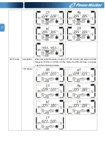
Page 28: ...arallel screen diagram The master UPS will be default assigned as 001 and slave UPSs will be assigned as either 002 or 003 The assigned numbers may be changed dynamically in the operation Parallel screen Operating mode status UPS Power On Description When UPS is powered on it will enter into this mode for a few seconds as initializing the CPU and system LCD display No output mode description When ...

Page 29: ...UPS will provide pure and stable AC power to output The UPS will also charge the battery at AC mode LCD display ECO mode Description When the input voltage is within voltage regulation range and ECO mode is enabled UPS will bypass voltage to output for energy saving LCD display ...

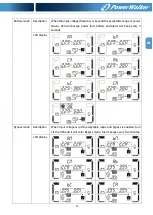
Page 30: ...CVCF mode Description When the output frequency is set to CF the inverter will output constant frequency 50 Hz or 60 Hz At this mode the UPS will have no bypass output but still charge battery LCD display ...

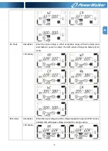
Page 31: ...e range or power failure UPS will backup power from battery and alarm will beep every 4 seconds LCD display Bypass mode Description When input voltage is within acceptable range and bypass is enabled turn off the UPS and it will enter Bypass mode Alarm beeps every two minutes LCD display ...

Page 32: ... users This operation is used to check the battery status LCD display Warning status Description If some errors occur in the UPS but it is still running normally it will show one more screen to represent the warning situation In the warning screen the icon will be flashing and it can show up to 3 error codes and each code indicates one error You can find the code meaning in the warning code table ...

Page 33: ...ult status Description When UPS has fault happened the inverter will be blocked It will display fault code in screen and the icon will light up You can find the code meaning in the fault code table LCD display ...

Page 34: ...e None 15 Inverter B output line to neutral short circuited 42 DSP communication failure None 16 Inverter C output line to neutral short circuited 43 Overload 17 Inverter A B output line to line short circuited 46 Incorrect UPS setting None 18 Inverter B C output line to line short circuited 47 MCU communication failure None 19 Inverter C A output line to line short circuited 48 Two DSP firmware v...

Page 35: ...play and alarm beeps every second EPO function is activated At this time the EPO switch is in OFF status or the jumper is open Set the circuit in closed position to disable the EPO function The icon and flash on LCD display and alarm beeps every second The external or internal battery is incorrectly connected Check if all batteries are connected well The icon and flash on LCD display and alarm bee...

Page 36: ... the UPS temperature is too high Check fans and notify dealer Symptom Possible cause Remedy The warning code 02 is shown the icon flashes on LCD display and alarm beeps every second The input neutral wire is disconnected Check and correct the input neutral connection If the connection is ok and the alarm is still displaying please refer to the LCD setting section to enter the neutral loss check me...

Page 37: ...he required precautionary measures may replace batteries and supervise operations Unauthorized persons must be kept well away from the batteries Verify that no voltage between the battery terminals and the ground is present before maintenance or repair In this product the battery circuit is not isolated from the input voltage Hazardous voltages may occur between the battery terminals and the groun...

Page 38: ...20 adjustable 2 x 20 18 20 adjustable 2 x 20 18 20 adjustable 3 x 20 18 20 adjustable Recharge Time 9 hours recover to 90 capacity Charging Current 1 0 A 10 max 2 0 A 10 max 2 0 A 10 max 4 0 A 10 max Charging Voltage 273 VDC 1 Long run Model Type Depending on applications Numbers 18 20 Charging Current 4 0 A 10 max 4 0 A 10 max 4 0 A 10 max 12 0 A 10 max Charging Voltage 273 VDC 1 PHYSICAL Outline...

Reviews: