background image


Document A55-00042 Rev. I  POWERVAR Mobile Power Manager 


P a g e

 | 12 

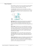
As the battery ages, the relative health of the battery will be reflected in the 

battery health

 meter.  The battery health meter reflects the calculated capacity 

of the battery “now”, relative to the original “like new” design capacity of the 
battery. 

The time available from the battery is a function of: 

o


The capacity of the battery (battery health) 

o


The energy remaining in the battery (fuel gauge) 

o


The energy demanded by your workstation (load) 

Input power state, battery charge and Alarms conditions will also be reflected 
on the dashboard as shown below: 


Details will also be logged on the local computer by MPMView software for later 
diagnosis by service Technicians via the advanced option “Tech View”). 

Summary of Contents for MPM

Page 1: ...rt numbers OEM variations Companion Documents A55 00042 00001 MPM RUI Clinic View End Users A55 00042 00002 MPMView_UM Rev Technicians A55 00049 ManageUPSCIO 2 0 MPM FleetView edition Licenses and Trademarks POWERVAR ONEAC are registered trademarks of POWERVAR Inc All other trademarks product and corporate names are the property of their respective owners Entire contents copyright 2014 POWERVAR Al...

Page 2: ...Remaining Fuel Gauge Warning Indicators 11 3 Technical Information for Engineering Service Personnel 14 Before You Start 14 Setup and Operation 15 5 Step Setup 15 NOTES ON POWER UP BEHAVIOR 18 System Overview Theory of Operations 19 System Overview 19 Theory of Operation 21 Technical Specifications 87023 06R 82023 07R 23 Physical Dimension Drawings 30 Remote User Interface RUI Description 32 Diagn...

Page 3: ...F THE MPM KEEP THIS MANUAL HANDY FOR REFERENCE CAUTION A BATTERY CAN PRESENT A RISK OF ELECTRICAL SHOCK SHORT CIRCUIT CURRENTS CAN BE EXTREMELY HIGH AND CAN CREATE SEVERE BURNS AS WELL AS THE RISK OF FIRE OR EXPLOSION FROM VENTED GASES ALWAYS OBSERVE PROPER PRECAUTIONS C CA AU UT TI IO ON N Safe and continuous operation of the MPM depends partially on the care taken by users NOTE THIS MPM POWER UN...

Page 4: ...PM Do not plug appliances such as hair dryers fans heaters etc into the MPM Do not place the MPM under direct sunshine or close to heat emitting sources The battery should be disconnected from the MPM by unplugging at its quick connectors when maintenance or service work inside the MPM is necessary A certified detachable power supply cord is to be used with this equipment For the 250VA models a ty...

Page 5: ...and or television reception which can be determined by turning the MPM equipment on and off the user is encouraged to try to correct the interference by one or more of the following measures 1 Reorient or relocate the receiving antenna 2 Increase the separation between the MPM and the receiver 3 Connect the MPM into an outlet on a circuit that is different from that to which the receiver is connec...

Page 6: ...Document A55 00042 Rev I POWERVAR Mobile Power Manager P a g e 6 ...

Page 7: ... er rs s This section of the Mobile Power Manager MPM Documentation Set covers the essential information that users of workstations and diagnostic instrumentation powered by the MPM should know o Plugging In for best Battery Health o Turning the output power On and Off o Understanding the Battery Fuel Gauge Health indicator o Service Indications ...

Page 8: ...he workstation computer Plug In for Best Battery Health The battery in your mobile cart is similar to the battery in your laptop computer If it is not charged from time to time the battery may not have enough charge remaining when you need it to work The MPM unit includes an automatic jump start circuit that will attempt to recover a weak battery Even so following the advice below will help keep y...

Page 9: ...Document A55 00042 Rev I POWERVAR Mobile Power Manager P a g e 9 put into extended storage mode by qualified Service technicians per instructions from the battery manufacturer ...

Page 10: ...ight on Green battery full 75 empty o light on Yellow blinking 1st Low Battery warning minutes remaining o light on Red blinking Critical Low Battery warning seconds remaining During recharge each light will blink slowly while that portion of the battery is being recharged For example 1st light ON 2nd light blinking means battery is between 25 and 50 charged etc Battery is not fully charged until ...

Page 11: ...attery The estimated time reported will adjust based on the actual electrical load of your workstation For example if your computer workstation enters a low power energy saving mode after some period of inactivity the estimated time available from the battery system will be recalculated and revised upward based on the reduced energy draw allow 10 20 seconds for dashboard information to be updated ...

Page 12: ...esign capacity of the battery The time available from the battery is a function of o The capacity of the battery battery health o The energy remaining in the battery fuel gauge o The energy demanded by your workstation load Input power state battery charge and Alarms conditions will also be reflected on the dashboard as shown below Details will also be logged on the local computer by MPMView softw...

Page 13: ...Document A55 00042 Rev I POWERVAR Mobile Power Manager P a g e 13 ...

Page 14: ... communications cables are connected as described in the Setup and Operation section p 18 before powering the unit NOTE For units connected to LiFePO4type batteries with smart battery communications interface1 the communications cable between the MPM unit and smart battery communication connection must be connected before energizing the MPM unit to prevent possible damage to the protection and man...

Page 15: ...e RUI and the other side of the RJ45 cable to the MPM RJ45 ports marked COMM1 COMM2 Note that the two cables for RUI must be properly connected for the RUI to operate COMM1 gray on unit to COMM1 gray on RUI COMM2 black to COMM2 black Ports and cables are also color coded black and gray for easier tracing from MPM unit in cart base to RUI location on work surface The control buttons and LED indicat...

Page 16: ...ower Manager P a g e 16 2 Connect the SMBus communications cable between MPM Smart Battery Connector and the Smart Battery Max length is 12 FAN EXHAUST COMMUNICATIONS PORT OUTPUT FUSE SMART BATTERY CONNECTION COMM 1 CONNECTION COMM 2 CONNECTION ...

Page 17: ...tteries 4 Attach the input AC line cord to the MPM via the IEC320 inlet connector Connect the input plug to 120V AC wall outlet When the MPM is connected to the AC wall outlet it will automatically charge the battery pack It is important to connect the MPM to a live AC outlet for a minimum of 4 hours LiFePO4 to 24 hours SLA to ensure full charge on the battery packs at initial installation 5 Conne...

Page 18: ...nt and float voltage that is safe for both SLA and LiFePO4 batteries Changing Battery Types The MPMView software can be used to reconfigure the unit for a different battery type The unit must be rebooted after changing the configuration this can be done from MPMView if the output is turned off and there is AC present on the input Cold Start Input AC NOT OK start from Battery If there is no input A...

Page 19: ... building branch circuits either 120VAC or 230VAC nominal to low voltage DC power 24VDC 5VDC for the internal system circuits Some power supplies are designed as universal power supplies to operate in either North American 120V 208V 60Hz or European 230V 50Hz AC power environments Universal power supplies are designed to provide a steady source of regulated DC output power across a wide range of A...

Page 20: ...c elements and basic control system as a UPM modified to operate from battery as the normal or primary power source for day to day activity MPM is different than a UPM in that it has a powerful charger system to allow faster recovery of battery charge And has power electronics designed for continuous operation without overheating ...

Page 21: ...nagement circuits BMS SOC Fuel Gauge The MPM uses its own internal algorithms for calculating actual state of charge and full charge capacity of the battery for battery health and fuel gauge reporting MPM also uses pre defined maximum and minimum VDC cut off thresholds to limit battery charge and discharge activities in the event SM Bus communications are not used or become disconnected or otherwi...

Page 22: ...g estimated time remaining from the battery during discharge TechView is used to configure an MPM update MPM unit firmware and view system information for analysis by service technicians These software products are described further in these companion documents A55 00042 00001 MPM RUI Clinic View End Users A55 00042 00002 MPMView_User Manual Technicians These documents and MPMView software can be ...

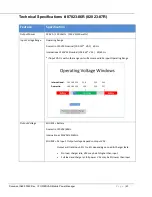
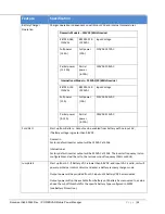
Page 23: ...l 195 265 VAC 50 60 Hz If input VAC is within the range unit will assume valid AC input Operating Range Output Voltage SOURCE Battery Domestic 120VAC 60Hz International 230VAC 50 60Hz SOURCE AC Input Output voltage depends on Input VAC Output will track Input 5 to 6 depending on Load Charger state No load charger idle VAC may be 6 higher than input Full load and charger at full power VAC may be 5 ...

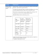
Page 24: ... from Battery Output can be enabled from battery with no input AC if battery voltage is greater than 9 8VDC Domestic Factory default inverter output will be 120VAC at 60Hz International Factory default inverter output will be 230VAC at 50Hz The inverter frequency is also configurable and will be set to the last seen input frequency 50Hz or 60Hz Jump Start Start up from AC If Battery VDC is lower t...

Page 25: ...urns the internal power supply is enabled and the unit starts up If the output was on prior to shut down it will automatically be turned on See also MPM post shutdown Auto Recovery section Overload Protection MPM OVERLOAD TABLE Line Mode Running on AC protection shut down delay Battery Mode Running on DC protection shut down delay 110 120 5 minutes 30 seconds 121 140 5 seconds 5 seconds 141 200 1 ...

Page 26: ...perature as measured on Bridge FET Heat Sink 1 DC mode MPM shuts down if T 90C 2 AC mode MPM turns off charger if T 80C MPM shuts down if T 90C MPM Auto Recovery operation after auto protective shutdowns Operating Mode before auto shutdown Restart Behavior Source Input AC line AC mode Auto Protective Shutdown due to over load or over temp MPM remains shutdown No automatic output restart Press outp...

Page 27: ...vice may be required Over Current Protections Input AC 8A 250V SLOW RESPONSE FUSE NON RESETTABLE INPUT LINE AND NEUTRAL I O PCB Return to Factory Output AC 1 6A TIME DELAYED FUSE NON RESETTABLE BUT REPLACEABLE OUTPUT LINE FRONT PANEL FUSEHOLDER Disconnect Load replace fuse and test Battery DC 2X30A AUTOMOTIVE FUSES NON RESETTABLE BATTERY RETURN MAIN PCB Return to factory All units have firmware th...

Page 28: ...a reduced current and float voltage that is safe for both SLA and LiFePO4 batteries It will also raise an alarm that the battery parameters need to be confirmed or changed Use MPMView software Advanced tab to set the battery type as either LiFePO4 without SMBus LP mode or SLA SE mode Then select the manufacturer and battery size in Ah Also enter the date the battery is new use install date and any...

Page 29: ...option via MPMView can disable the audible alarm so that it will never sound during operation Warning indications will be visible via RUI LEDs or MPMView software dashboard only Audible noise Fan operation 45 dBA at 1 meter Mechanical Electronics Enclosure 3 5 high x 6 1 W x 11 46 D adequate clearance for input and output airflow required Battery Enclosure none Weight 15 0 lbs 6 8 kg 15 5 lbs 7 0 ...

Page 30: ...Document A55 00042 Rev I POWERVAR Mobile Power Manager P a g e 30 Physical Dimension Drawings ...

Page 31: ...Document A55 00042 Rev I POWERVAR Mobile Power Manager P a g e 31 ...

Page 32: ... of RUI implementations POWERVAR and 3rd Party T Type POWERVAR RUI In the POWERVAR design the warning indictor LEDs is separated from the Battery Charge Gauge 3rd Party T type RUI In the 3rd party RUI design the warning indicator LEDs are typically placed within the fuel gauge and shared with the lower two charge level LED indicators ...

Page 33: ...FF OFF ON ON ON OFF OFF 26 50 OFF OFF ON ON OFF OFF OFF 0 25 OFF OFF ON OFF OFF OFF OFF Bootup First 4 seconds OFF OFF OFF RED OFF OFF ON OFF ON OFF Button can be pressed at any time during this period to turn unit on Warning Alarms YEL OFF OFF OFF OFF OFF OFF Flash LED2 1x per sec Severe Alarms OFF RED OFF OFF OFF OFF ON Flash LED3 1x per sec Buzzer beeps 2x per second Mute button silences Inform...

Page 34: ...OFF ON OFF Button can be pressed at any time during this period to turn unit on Warning Alarms YEL YEL OFF OFF OFF Flash LED2 and LED3 1x per second Severe Alarms RED RED OFF OFF ON Flash LED2 and LED3 1x per second Buzzer beeps 2x per second Mute button silences Informational Alarms Informational alarms do not require special handling NOTES Battery Low LED 2 Flashing Yellow ON for 1 second OFF fo...

Page 35: ...ne voltage to the MPM is within specified boundaries Problem Possible Cause Action you should take MPM does not power up and has no audible alarm On Off button is not pressed long enough Press and hold the On Off switch for at least 3 seconds Invalid Battery and Invalid Input AC Check wall socket and test for proper line voltage MPM input power cord is not plugged in Plug in input power cord Outpu...

Page 36: ...hed Default thresholds are 7 or 5 minutes These can be modified using MPM TechView 20 147 Lost Device Communications MPMView is unable to communicate with MPM unit This could be caused by the USB cable being disconnected the USB port on the computer has failed or the MPM is off It is not likely that the MPM will be off in normal usage however it is possible in lab settings when PC running MPMView ...

Page 37: ...y Connection The MPM unit detects no voltage across the battery terminals Battery may be disconnected or there may be a blown fuse The MPM can still power up when connected to AC input line 30 189 Input Frequency Out Of Range This alarm is raised if the frequency of the input AC power to the MPM unit is out of range and the output can only be supplied from battery power 34 053 Battery Charge Thres...

Page 38: ...red by any unauthorized personnel or where evidence of tampering exists The foregoing constitutes the sole and exclusive remedy of the purchaser and is in lieu of all other warranties No greater degree of liability is imposed on POWERVAR Battery If batteries are included as part of the system delivered from POWERVAR SLA batteries are warranted to be free from defects in materials or workmanship fo...

Page 39: ...s the use of its products in these applications and under no conditions will POWERVAR knowingly sell any of its products for such uses Any use in such applications is purely without the knowledge or consent of POWERVAR who disavows any liability for such use Any buyer who uses a POWERVAR product for such applications acknowledges that POWERVAR has provided buyer with this disclaimer and that buyer...

Page 40: ...e Illinois 847 596 7000 Fax 847 596 7100 www powervar com Copyright POWERVAR Inc 2013 All rights reserved POWERVAR is a trademark of POWERVAR Inc Waukegan IL Other trademarks may be pending No part of this manual may be reproduced or distributed either electronically or in printed form without the express written permission of POWERVAR Inc 2013 ...

Reviews: