31
A01-00030 Rev D
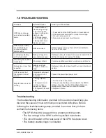
7.0 TROUBLESHOOTING
Troubleshooting
The troubleshooting information provided in this section should help you
discover the cause of most commonly encountered difficulties. Before
following the troubleshooting steps provided, be certain that you have
verified the following items:
•The UPM should be plugged into a properly working outlet.
• The line voltage to the UPM is within specified boundaries.
• The circuit breaker on the rear panel of the UPM has been reset.
• The battery enable plug(s) is installed.
Problem
Possible Cause
Action you should take
UPM does not power
up and has no audible
alarm
1. On/Off Button not
pressed long enough
2. No incoming line
voltage or voltage too
high or too low
3. UPM input power
cord is not plugged in
4. Rear panel circuit
breaker is tripped
1. Press and hold the On/Off switch for 3 seconds min.
2. Check wall socket and test for proper line voltage.
3. Plug in input power cord.
4. Reduce load and reset circuit breaker.
UPM Overload LED’s
are illuminated and
continuous audible
alarm sounds
UPM is overload
Reduce load by removing the least critical load items
from the UPM output.
Low/Replace Battery
LED is illuminated
Battery voltage is too
low or battery is dead
Recharge battery for at least six hours and reset UPM. If
LED is still illuminated, replace the battery.
Site Wiring Fault LED is
illuminated
Site wiring problem
Contact a qualified electrician to verify wiring at this site.
Backup time is less than
expected
Battery is not fully
charged or battery is
dead
Recharge battery for at least eight hours and retest back
up time.
UPM is normal, but
the computer will not
turn on.
Computer input power
cord is loose or not
connected
Connect the power input power cord.
MopUPS Express is not
working
1. Wrong interface
cable
2. Computer’s serial
port has not been
properly configured
3. Computer’s I/O card
is bad
1. Purchase the correct cable.
2. Check to see that the port is enabled in the CMOS
settings. Also check for the IRQ conflicts. Make sure
settings match those found in MopUPS Express.
3. Replace I/O card.
Summary of Contents for GTS Series
Page 1: ...GTS Series User Manual ...
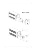
Page 24: ...24 A01 00030 Rev D Figure 2 250 400VA Figure 3 600VA ...
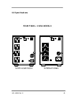
Page 25: ...25 A01 00030 Rev D 6 0 Specifications REAR PANEL 250VA MODELS INTERNATIONAL NORTH AMERICAN ...
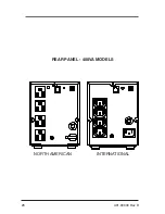
Page 26: ...26 A01 00030 Rev D REAR PANEL 400VA MODELS INTERNATIONAL NORTH AMERICAN ...
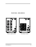
Page 27: ...27 A01 00030 Rev D REAR PANEL 600VA MODELS INTERNATIONAL NORTH AMERICAN ...
Page 33: ...33 A01 00030 Rev D ...
Page 56: ...56 A01 00030 Rev D Figure 2 250 400VA Figure 3 250 600VA ...
Page 58: ...58 A01 00030 Rev D PANNEAU ARRIÈRE MODÈLES 400VA INTERNATIONAL AMÉRIQUE DU NORD ...
Page 59: ...59 A01 00030 Rev D PANNEAU ARRIÈRE MODÈLES 600VA INTERNATIONAL AMÉRIQUE DU NORD ...
Page 65: ...65 A01 00030 Rev D ...

