21
A01-00030 Rev D
These batteries use a non-liquid electrolyte, which makes it possible to
use them in any physical orientation. The batteries are designed to last
from two to five years. Their actual life span will depend on several factors
including how often power outages occur, how long power outages last,
and the temperature of the environment in which the UPM operates.
Frequent, long duration power outages will shorten battery life more than
infrequent, short duration outages. Consistent high temperatures in the
area where the UPM is used will also shorten battery life.
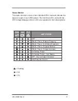
The UPM is equipped with a Low/Replace Battery LED on the front
panel. If the LED illuminates, you should make sure that the battery has
at least six hours to charge without a power interruption. Inadequate
(much shorter than usual) backup time, premature low battery alarm
sounds, and persistent Low/Replace Battery LED illumination are all
good signs that the batteries inside your UPM requires replacement.
The batteries inside your UPM are designed to be easily replaced by a
user who possesses basic mechanical/electrical knowledge and simple
tools. Please familiarize yourself with the following precautions before
proceeding with battery replacement.
WARNING
Servicing of batteries should always be performed or supervised by
someone who has read and understood the following precautions and
who understands the hazards associated with storage batteries. This
procedure should not be performed by someone who is unauthorized or
who is incapable of following these precautions.
CAUTION
• Only the battery assembly in this unit is user serviceable. The
battery compartment is accessed by removing the front panel as
described in the following instructions. No other user serviceable
parts are contained in this UPM. Do not remove any cover other
than the front battery access panels.
• A battery (even a depleted one) can deliver very high currents when
short-circuited. There is a danger of electrical shock. Remove all
Summary of Contents for GTS Series
Page 1: ...GTS Series User Manual ...
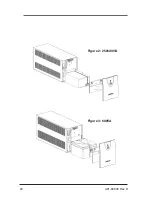
Page 24: ...24 A01 00030 Rev D Figure 2 250 400VA Figure 3 600VA ...
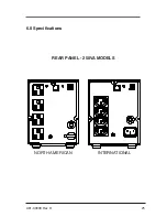
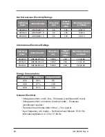
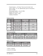
Page 25: ...25 A01 00030 Rev D 6 0 Specifications REAR PANEL 250VA MODELS INTERNATIONAL NORTH AMERICAN ...
Page 26: ...26 A01 00030 Rev D REAR PANEL 400VA MODELS INTERNATIONAL NORTH AMERICAN ...
Page 27: ...27 A01 00030 Rev D REAR PANEL 600VA MODELS INTERNATIONAL NORTH AMERICAN ...
Page 33: ...33 A01 00030 Rev D ...
Page 56: ...56 A01 00030 Rev D Figure 2 250 400VA Figure 3 250 600VA ...
Page 58: ...58 A01 00030 Rev D PANNEAU ARRIÈRE MODÈLES 400VA INTERNATIONAL AMÉRIQUE DU NORD ...
Page 59: ...59 A01 00030 Rev D PANNEAU ARRIÈRE MODÈLES 600VA INTERNATIONAL AMÉRIQUE DU NORD ...
Page 65: ...65 A01 00030 Rev D ...


