


Powertronix spa reserves the right to modify this document without notice
Page 22 of 46
R&D – USER MANUAL DT0430-E04
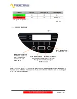
2.7.2. REMOTE PANEL (Optional)
Remote panel is connected to the UPS via the terminal board M1 located on the remote communication
board (CS0098)(connection diagram fig. 2.7.2a). This device is used for remote monitoring of the main
UPS blocks, the status of the main blocks is represented through LED, and there is also an acoustic alarm,
which can be shut off with key 5.
LED description :
1) Green ON UPS LED
If it’s on, the UPS is operating correctly
If it’s off, indicates that one or more inverter section alarms are present
(acoustic alarm enabled)
2)Yellow ON BATTERY LED
If it’s on, the UPS is operating on battery
(acoustic alarm enabled)
3) Red LOW BATTERY LED
If it’s on, indicates imminent end of battery discharge
(acoustic alarm enabled)
4) Yellow ON BYPASS LED
If it’s on, indicates load supplied from reserve
(acoustic alarm enabled)
5) ALARM SILENCE key
Used to switch off the acoustic alarm
6) Green LED
If it’s on, indicates correct power supply connected to the panel
1
2
3
4
5
6
7
8
9
10
11
12
DB9
Male Connector
5
9
4
8
3
7
2
6
1
K1
12V-12A
4
5
3
1
2
1
2
3
4
5
6
7
8
CS0098 Relay Board
M1
UPS Remote
Panel
Mains Status
Battery LOW
On By-Pass
M1
Common
Ups ON
EXT SUPPLY
ON CS0098 COMMON TAGBLOCKS (2-5-8-11)
MUST BE CONNECTED TOGETHER
NOTE:
1
2
3
4
5
1
9
6
2-5-8-11
CS0098
Relay
Board
UPS
REMOTE
PANEL
12
Fig. 2.7.2b


