Service Manual
PCB Replacement Procedures
7 - 36
3x3 UPS
Issue 2 - November 2001
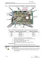
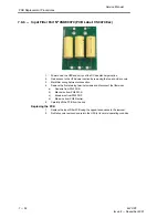
7.9.6 - Input Filter Part Nº 0SDE0079 (PCB Label: CS0079 Exx)
1.
Power down the UPS and carry out the DC bus discharge routine.
2.
Gain access to the UPS power section by removing the top and side covers.
3.
Mark filter wiring before disconnection.
4.
Remove the five retaining terminal screws and disconnect the filter wires.
a)
Red wire from PW3 PHĆR.
b)
Black wire from PW4 PHĆS.
c)
Brown wire from PW5 PHĆT.
d)
Blue wire from PW2 Neutral.
5.
Carefully lift the PCB from the unit.
Replacing the PCB
1.
Replace the Input Filter PCB using the opposite sequence to the removal.
2.
Refit all covers removed and return the UPS to its normal operating condition.

