background image


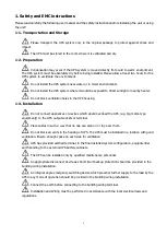
1. Safety and EMC instructions 


Please read carefully the following user manual and the safety instructions before installing the unit or using 

the unit! 

1-1. Transportation and Storage 

  Please  transport  the  UPS  system  only  in  the  original  package  to  protect  against  shock  and 

impact. 

  The UPS must be stored in the room where it is ventilated and dry. 

1-2. Preparation 

  Condensation may occur if the UPS system is moved directly from cold to warm environment. 

The UPS system must be absolutely dry before being installed. Please allow at least two hours for the 

UPS system to acclimate the environment.   

  Do not install the UPS system near water or in moist environments. 

  Do not install the UPS system where it would be exposed to direct sunlight or nearby heater. 

  Do not block ventilation holes in the UPS housing. 

1-3. Installation 

  Do not connect appliances or devices which would overload the UPS (e.g. big motor-type 

equipment)) to the UPS output sockets or terminal.   

  Place cables in such a way that no one can step on or trip over them.   

  Do not block air vents in the housing of UPS. The UPS must be installed in a location with good 

ventilation. Ensure enough space on each side for ventilation.   

  UPS has provided earthed terminal, in the final installed system configuration, equipotential 

earth bonding to the external UPS battery cabinets. 

  The UPS can be installed only by qualified maintenance personnel. 

  An appropriate disconnect device as short-circuit backup protection should be provided in the 

building wiring installation. 

  An integral single emergency switching device which prevents further supply to the load by the 

UPS in any mode of operation should be provided in the building wiring installation.   

  Connect the earth before connecting to the building wiring terminal.   

  Installation and Wiring must be performed in accordance with the local electrical laws and 

regulations.   


Summary of Contents for Centurion RT 6000VA

Page 1: ......

Page 2: ...instructions in this manual strictly Save this manual properly and read carefully the following instructions before installing the unit Do not operate this unit before reading through all safety info...

Page 3: ...INSTALLATION 6 2 5 UPS INSTALLATION FOR PARALLEL SYSTEM 8 2 5 SOFTWARE INSTALLATION 8 3 OPERATIONS 9 3 1 BUTTON OPERATION 9 3 2 LED INDICATORS AND LCD PANEL 9 3 3 AUDIBLE ALARM 11 3 4 SINGLE UPS OPERA...

Page 4: ...nect appliances or devices which would overload the UPS e g big motor type equipment to the UPS output sockets or terminal Place cables in such a way that no one can step on or trip over them Do not b...

Page 5: ...inals may be live when the UPS is not connected to an AC supply 1 5 Operation Do not disconnect the earth conductor cable on the UPS or the building wiring terminals in any time since this would cance...

Page 6: ...00 4 3 Level 3 EFT IEC EN 61000 4 4 Level 4 SURGE IEC EN 61000 4 5 Level 4 CS IEC EN 61000 4 6 Level 3 Power frequency Magnetic field IEC EN 61000 4 8 Level 4 Low Frequency Signals IEC EN 61000 2 2 Wa...

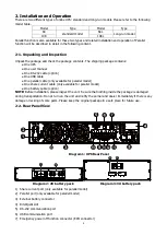
Page 7: ...y available for parallel model One share current cable only available for parallel model One battery cable option NOTE Before installation please inspect the unit Be sure that nothing inside the packa...

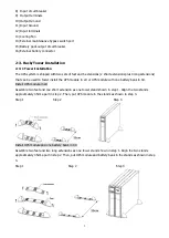
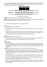
Page 8: ...n be used to tower install the UPS module in 2U or UPS module with one battery bank in 4U Install UPS module in 2U Assemble two feet and one short extension as one tower stand shown in step 1 Align th...

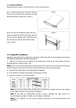
Page 9: ...city of UPS to avoid the hazards of electric shock or fire NOTE Do not use the wall receptacle as the input power source for the UPS as its rated current is less than the UPS s maximum input current O...

Page 10: ...tall it carefully Switch off the battery breaker before installation Warning For standard battery pack there is one DC breaker to disconnect the battery pack and the UPS But for other external battery...

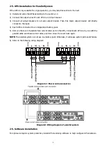
Page 11: ...h UPS is connected to an independent battery pack 5 Remove the cover of parallel share current cable port on the UPS connect each UPS one by one with the parallel cable and share current cable and the...

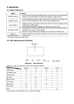
Page 12: ...isplay next selection in setting menu Mute Down Button Mute the alarm Press and hold the button more than 0 5s to mute the buzzer Please refer to section 3 4 9 for details Down key Press this button t...

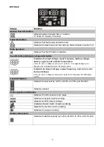
Page 13: ...ltage A ampere percent centigrade degree Hz frequency AC alternating current DC direct current Indicate the output voltage output frequency load current and load percentage k kilo W watt V voltage A a...

Page 14: ...e UPS will operate in Battery mode without interruption NOTE When the UPS is running out battery it will shut down automatically at Battery mode When the utility power is restored the UPS will auto re...

Page 15: ...no more load to be switched off at that time you have to shut down all loads as soon as possible to protect the devices or save data Otherwise there is a risk of data loss or load failure 2 In Battery...

Page 16: ...ble shooting table in chapter 4 for details 2 Please check the loads wiring ventilation utility battery and so on after the fault occurs Don t try to turn on the UPS again before solving the problems...

Page 17: ...Program 15 section 3 7 in LCD setting If voltage difference remains more than 1 5V after calibration please contact your local distributor or service center for help 2 Calibrate the output voltage me...

Page 18: ...unit 3 After it shuts down you can turn off the battery breaker for long run model and remove the parallel cable and share current cable Then remove the unit from the parallel system Second method 1...

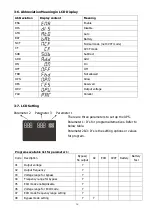
Page 19: ...ameter 1 There are three parameters to set up the UPS Parameter 1 It s for program alternatives Refer to below table Parameter 2 3 It s is the setting options or values for program Programs available...

Page 20: ...ameter 2 50 0Hz The output frequency is setting for 50 0Hz 60 0Hz The output frequency is setting for 60 0Hz At If selected output frequency will be decided according to the latest normal utility freq...

Page 21: ...range is from 51 0Hz to 54 0 Hz 60 Hz Setting range is from 61 0Hz to 64 0Hz The default value is 54 0Hz 64 0Hz 05 ECO mode enable disable Interface Setting Parameter 3 Enable or disable ECO function...

Page 22: ...utomatic bypass is acceptable but manual bypass is not allowed Manual bypass means users manually operate UPS for Bypass mode For example pressing OFF button in AC mode to turn into Bypass mode 09 Bat...

Page 23: ...0V to 5 7V the default value is 0V 14 Charger voltage adjustment Interface Setting Parameter 2 you may choose Add or Sub to adjust charger voltage Parameter 3 the voltage range is from 0V to 9 9V the...

Page 24: ...2 battery numbers setting Set the battery numbers ranging from 16 20 After pressing Enter button to confirm selection then it will show charger status in Parameter 1 Parameter 3 charger status settin...

Page 25: ...LCD display CVCF mode Description When input frequency is within 46 to 64Hz the UPS can be set at a constant output frequency 50 Hz or 60 Hz The UPS will still charge battery under this mode LCD displ...

Page 26: ...t code Icon Bus start failure 01 None Battery SCR short circuited 21 None Bus over 02 None Inverter relay short circuited 24 None Bus under 03 None Charger short circuited 2a None Bus unbalance 04 Non...

Page 27: ...ry second Battery unconnected Beeping every second 3 11 Warning Code Warning code Warning event Warning code Warning event 01 Battery unconnected 10 L1 IP fuse broken 07 Over charge 21 Line situations...

Page 28: ...Remove excess loads from UPS output first Then shut down the UPS and restart it Fault code is shown as 43 The icon lights on LCD display and alarm beeps continuously UPS is overload too long and beco...

Page 29: ...required precautionary measures may replace batteries and supervise operations Unauthorized persons must be kept well away from the batteries Verify that no voltage between the battery terminals and...

Page 30: ...27 6 Specifications...
Page 31: ...ing and inspection charge will apply as above 11 For hardwired products larger than 3KVA the warranty covers onsite repair for metro areas in capital cities only For equipment installed in remote loca...

Reviews: