10
Read and understand the entire
contents of this manual before attempting set-
up or operation. Failure to comply may cause
serious injury.
NOTE: Figures in this manual may show the lathe
with optional accessories, which are purchased
separately.
6.0
Setup and Assembly
6.1
Unpacking
Open shipping container and check for shipping
damage. Report any damage immediately to your
distributor and shipping agent. Do not discard any
shipping material until the Lathe is assembled and
running properly.
Compare the contents of your container with the
following parts list to make sure all parts are intact.
Missing parts, if any, should be reported to your
distributor. Read the instruction manual thoroughly
for assembly, maintenance and safety instructions.
6.2
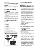
Contents of shipping container
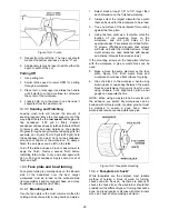
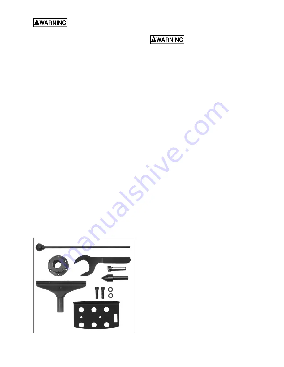
See Figure 6-1.
1 Lathe with headstock, tailstock, and tool rest
base (not shown)
1 Knockout
rod
1 Face plate 3in.
1 Face
plate
wrench
1 Toolrest, 8in.
1 Spur center 1in.
1 Cone live center
2 Socket head cap screws, 3/8 x 1-1/4
2 Flat washers, 3/8
1 Tool
caddy
1 Owner's manual (not shown)
1 Product registration card (not shown)
Figure 6-1: accessories included
6.3
Tools required for assembly
8mm hex key (“Allen wrench”)
The Lathe must be discon-
nected from power during assembly. Use an
assistant or a hoist to help lift items.
1. Remove any screws or straps that hold the
Lathe parts to the pallet, and remove protective
wrapping. Set all boxes containing accessories
to the side.
2. The Lathe should be located in a dry area, on a
sturdy bench or the Powermatic accessory
stand (#1792014S), and with sufficient lighting.
Leave plenty of space around the machine for
operations and routine maintenance work.
(If the accessory stand was purchased, refer to
the assembly instructions that accompany it.)
3. Exposed metal areas of the Lathe, such as bed
ways and spindles, have been factory coated
with a protectant. This should be removed with
a soft cloth and a cleaner-degreaser. Clean the
bed areas under headstock, tailstock and tool
support base. Do not use an abrasive pad, and
do not allow solvents to contact painted or
plastic areas.
4. Apply a light coat of SAE10 oil to the exposed
metal areas to impede rust.
6.4
Tool caddy
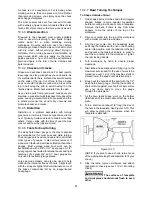
The tool caddy may be mounted to the lathe bed
with the provided screws and washers. See Figure
5-1.
6.5
#6294755 Bed extension
(OPTIONAL)
If you did not purchase the optional 13-inch bed
extension, proceed to sect. 6.6.
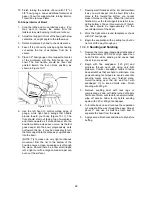
To mount bed extension to Lathe:
1. Slide tailstock away from edge of bed, and
unscrew stud (A, Figure 6-2).
2. Have an assistant hold bed extension flush to
end of Lathe bed, and insert four 3/8 x 1-3/4
socket head cap screws with lock washers and
flat washers (provided with extension bed)
through holes in bed extension into threaded
holes on Lathe (8mm hex wrench). Make
screws snug but do not fully tighten. See Figure
6-2.
3. Adjust extension bed to lathe bed, aligning top
surface and inside ways as closely as possible.
Make screws snug but
do not fully tighten yet
.
4. Slide tailstock over joint where beds meet, so
that clamping nut is centered over joint, as
shown in Figure 6-2. Firmly tighten tailstock
clamping handle; this will align the beds.
Summary of Contents for PM2014
Page 27: ...27 15 1 1 PM2014 Headstock Assembly Exploded View ...
Page 30: ...30 15 2 1 PM2014 Bed Toolrest and Tailstock Assemblies Exploded View ...
Page 35: ...35 16 0 Electrical connections PM2014 Lathe cont next page ...
Page 36: ...36 cont ...
Page 38: ...38 This page intentionally left blank ...
Page 39: ...39 This page intentionally left blank ...
Page 40: ...40 427 New Sanford Road LaVergne Tennessee 37086 Phone 800 274 6848 www powermatic com ...


