background image

 40 


427 New Sanford Road 

LaVergne, Tennessee 37086 

Phone: 800-274-6848 
www.powermatic.com 


Summary of Contents for PM2014

Page 1: ...o M 1792014 Ph 800 274 6848 Edition 1 11 2019 www powermatic com Copyright 2019 Powermatic Operating Instructions and Parts Manual 20 x14 Benchtop Woodturner s Lathe Model PM2014 Shown with optional stand 1792014S ordered separately This pdf document is bookmarked ...

Page 2: ...ments or maintenance with the machine unplugged from the power source 13 Remove adjusting keys and wrenches Form a habit of checking to see that keys and adjusting wrenches are removed from the machine before turning it on 14 Keep safety guards in place at all times when the machine is in use If removed for maintenance purposes use extreme caution and replace the guards immediately after maintenan...

Page 3: ...mp up to operating speed 35 Never stop a rotating workpiece with your hand 36 If gluing up a workpiece always use a high quality glue of the type necessary for that particular workpiece Familiarize yourself with the following safety notices used in this manual This means that if precautions are not heeded it may result in minor injury and or possible machine damage This means that if precautions a...

Page 4: ... complete instruction guide for woodturning practices choice of stock use of after market accessories etc Additional knowledge may be obtained from experienced users or trade articles Whatever accepted methods are used always make personal safety a priority If there are questions or comments about this product please contact your local supplier or Powermatic Powermatic can also be reached at our w...

Page 5: ... switch 16 9 2 Remote switch box 16 9 3 Variable frequency drive inverter 16 10 0 Operation 17 10 1 Inspection 17 10 2 Turning tools 17 10 3 Spindle turning 18 10 4 Face plate and bowl turning 20 11 0 User maintenance 23 11 1 Additional servicing 23 12 0 Optional Accessories 24 13 0 Troubleshooting PM2014 Lathe 25 14 0 Recommended lathe speeds per diameter of workpiece 26 15 0 Replacement parts 26...

Page 6: ...g distance between centers with 13 optional bed extension mounted 32 1 4 in 819mm with stop bolts installed Inboard turning Swing over bed 14 1 4 in 362 mm Swing over toolrest base 10 3 4 in 273 mm Outboard turning Recommended maximum spindle load 3 356 kg 786 lbs at 100mm 4 in from spindle flange Swing over optional 13in bed extension in low position 20 1 4 in 514 mm Swing over toolrest base on o...

Page 7: ...83 lbs 83 kg Shipping weight 205 7 lbs 93 5 kg Stand optional Net weight 55 lbs 25 kg Shipping weight 63 8 lbs 29 kg 13 in Bed extension optional Net weight 29 lbs 13 kg Shipping weight 30 8 lbs 14 kg 1 Subject to local national electrical codes 2 The specified values are emission levels and are not necessarily to be seen as safe operating levels As workplace conditions vary this information is in...

Page 8: ...securing the PM2014 Workbench holes will be clearance holes for 5 16 screws Holes in lathe base are threaded 5 16 18 3 4 in deep Only four of the holes need be used when mounting to a workbench Use four 5 16 18 bolts of appropriate length with washers insert through workbench and into lathe base Figure 4 1 mounting pattern for workbench ...

Page 9: ...ool rest base locking handle 15 Remote switch box 16 Tailstock 17 Tailstock handwheel 18 Hole through tailstock spindle 19 Tailstock spindle locking handle 20 Tailstock spindle 21 Tailstock locking handle 22 Stud x2 23 Live cone center 24 Spur center 25 Spindle 26 Variable frequency drive Inverter 27 Headstock locking handle 28 Bed ways 30 ID serial no label 31 Motor label 32 Mounting holes for op...

Page 10: ...be located in a dry area on a sturdy bench or the Powermatic accessory stand 1792014S and with sufficient lighting Leave plenty of space around the machine for operations and routine maintenance work If the accessory stand was purchased refer to the assembly instructions that accompany it 3 Exposed metal areas of the Lathe such as bed ways and spindles have been factory coated with a protectant Th...

Page 11: ...ne must be properly grounded to help prevent electrical shock and possible fatal injury The Lathe will operate on single phase 120 volt power supply The Variable Frequency Drive or inverter converts the incoming power to the necessary input for the 3 phase motor It is recommended that the lathe be connected to a 15 amp circuit with circuit breaker or time delay fuse Local codes take precedence ove...

Page 12: ...l cause a drop in line voltage resulting in loss of power and overheating Table 2 shows correct size to use depending on cord length and nameplate ampere rating If in doubt use the next heavier gauge The smaller the gauge number the heavier the cord Amp Rating Volts Total length of cord in feet More Than Not More Than 120 25 50 100 150 AWG 0 6 18 16 16 14 6 10 18 16 14 12 10 12 16 16 14 12 12 16 1...

Page 13: ...dle and is used to create evenly spaced features in a workpiece while keeping the lathe spindle locked for example when cutting flutes on a spindle blank with a router while the spindle blank is secured between lathe centers Numbers 1 through 24 are inscribed on top sheave K Figure 8 4 for reference When lathe is powered however the LED display can be used for rapid locating of index positions as ...

Page 14: ...athe from power source 2 Mount faceplate to your bowl blank 3 Pull up spindle lock tab Figure 8 7 and rotate handwheel until lock engages spindle Continue holding tab in raised position 4 Install faceplate onto threads of headstock spindle and rotate clockwise hand tight When the Lathe is turned on forward rotation the rotational force will snug the faceplate even farther onto the threads If at an...

Page 15: ...le M to raise motor 3 Tighten lock handle L to hold motor in raised position Slip belt off lower pulley 4 Loosen two set screws on handwheel P Figure 8 9 with a 3mm hex wrench and unscrew handwheel off spindle NOTE Left hand threads rotate clockwise to loosen 5 Tap left end of spindle with a rubber mallet or a steel face hammer against a block of wood to push it to the right just enough to remove ...

Page 16: ... control dial Always start Lathe at lowest speed with dial rotated all the way counter clockwise E Index button Push to set index reference to zero See sect 8 5 Figure 9 1 operating controls 9 3 Variable frequency drive inverter The PM2014 Lathe uses the latest technology in A C inverter drives to provide infinitely variable spindle speeds within the specified ranges The inverter controls the spee...

Page 17: ...1 1 4 used to make finishing cuts and details Large Roughing Gouge 1 to 1 1 4 used to eliminate waste wood Spindle Gouges 1 4 3 8 1 2 used to turn beads coves and other details Deep Fluted Bowl Gouge 1 4 3 8 and 1 2 used for turning bowls plates Square Scraper Bedan 3 8 or 1 2 used to create square shoulders Large Round Nose Domed Scraper 1 1 2 used to reduce ridges on interior of bowls round edge...

Page 18: ...Figure 10 4 Be careful that you do not split the workpiece Never use a steel face hammer and never drive the workpiece onto the spur center while it is mounted in the Lathe spindle 4 Make sure the headstock is locked to the Lathe bed 5 Clean the tapered end of the spur center and the inside of the headstock spindle 6 Insert the tapered end of the spur center with the attached workpiece into the he...

Page 19: ...Make a parting cut for what is to be a bead to the desired depth Place the parting tool on the tool support and move tool forward to make the full bevel of the tool come into contact with the workpiece Gently raise handle to make cut to the appropriate depth 2 Repeat for other side of the bead 3 Using a small skew or spindle gouge start in the center between the two cuts and cut down each side to ...

Page 20: ... face plate is the most common method for holding a block of wood for turning bowls and plates 1 Select stock at least 1 8 to 1 4 larger than each dimension on the finished workpiece 2 Always select the largest diameter face plate that can be used for the workpiece to be turned 3 True one surface of the workpiece for mounting against the face plate 4 Using the face plate as a template mark the loc...

Page 21: ...emoval of wood much faster and with less vibration than other gouges Most average sized bowl work can be accomplished with a 3 8 or 1 2 bowl gouge A 1 4 bowl gouge is best suited for smaller bowls and light finishing cuts Larger 3 4 and 1 bowl gouges are only used for extremely large pieces Large domed scrapers can also be used to help clean up the interior surfaces of bowls A light touch with the...

Page 22: ...ew small ridges left a light cut with a large domed scraper can even out the surface 7 Develop wall thickness at the rim and maintain it as you work deeper into the bowl Once the piece is thin toward the bottom you cannot make it thinner at the rim When the interior is finished move the tool support to exterior to re define bottom of bowl General rule of thumb the base should be approximately 1 3 ...

Page 23: ... any rust spots that may develop on the bed with a commercial rust remover Extend the tailstock quill and wipe on a light coat of SAE10 oil with a soft rag Avoid getting oil inside the quill where the center is inserted Use compressed air or a vacuum in the headstock interior in order to keep sawdust and chips from accumulating on belts and sheaves CAUTION Wear safety glasses when using compressed...

Page 24: ...nce the functionality of your PM2014 lathe These items are purchased separately contact your Powermatic dealer for more information 6294755 13 inch bed extension with tool post riser PM2014 TEA Tool rest extension 6294732 Heavy duty outboard turning stand JWL1442 205 12 inch tool rest ...

Page 25: ...eplace potentiometer Electronic AC inverter is not programmed properly or is defective or there is loose wiring Contact Powermatic Technical Service to help identify problem 800 274 6846 Tools tend to grab or dig in Dull tools Keep tools sharp Tool support set too low Reposition tool support height Tool support set too far from workpiece Reposition tool support closer to workpiece Improper tool be...

Page 26: ...Replacement parts Replacement parts are listed on the following pages To order parts or reach our service department call 1 800 274 6848 Monday through Friday 8 00 a m to 5 00 p m CST Having the Model Number and Serial Number of your machine available when you call will allow us to serve you quickly and accurately Non proprietary parts such as fasteners can be found at local hardware stores or may...

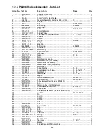
Page 27: ...27 15 1 1 PM2014 Headstock Assembly Exploded View ...

Page 28: ...an Cover not shown 1 PM2014 JB Junction Box not shown 1 PM2014 JBC Junction Box Cover not shown 1 24 PM2014 124 Motor Label 1 25 TS 0720081 Spring Washer 5 16 1 26 TS 0208071 Socket Head Cap Screw 5 16 18x1 1 4 1 27 TS 0680031 Flat Washer 5 16 1 28 JWL1015 137 Lock Handle 3 8 16x1 1 29 3520C 148 Magnet 2 30 F010878 Flat Head Socket Screw M3 0 5x10 1 31 TS 1482011 Hex Cap Screw M6 1 0Px10 1 32 PM20...

Page 29: ...Screw 10 24x1 2 2 76 JWL1221VS 269E Wrench includes 77 1 77 JWL1221VS 270 Rubber Cover 1 78 PM2014 177 Knock Out Rod 1 79 PM2014 179 Grounding Wire 1 80 PM2014 180 Belt 160J 6 1 82 PM2014 182 Set Screw 10 24x1 2 1 83 PM2014 183 Motor Cable 1 84 3520C 14110 Signal Cable Remote switch box to Inverter 1 85 3520C 181 Signal Cord Inverter box to Encoder PCB box 1 86 PM2014 186 Bung 1 87 JML 8 Wave Wash...

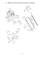
Page 30: ...30 15 2 1 PM2014 Bed Toolrest and Tailstock Assemblies Exploded View ...

Page 31: ... PM2014 TA Tailstock Assembly item 20 thru 37 20 JWL1440 219 Quill MT 2 1 21 JWL1440 220 Lead Screw 1 22 PM2014 222 Tailstock 1 23 PM2014 223 Tailstock Handwheel 1 24 PM2014 224 Tailstock Handwheel Handle 1 25 6295796 Set Screw 1 26 6295910 Lock Handle 1 27 3728005 Quill Lock Sleeve 1 28 JWL1221VS 227 Key 1 29 PM2014 229 Socket Head Round Screw 10 32x3 4 1 30 PM2014 230 Eccentric Rod Tailstock 1 3...

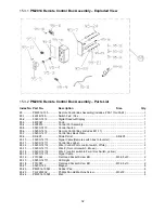
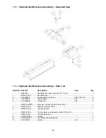
Page 32: ...417 Control Box Back Plate 1 95 9 SR 6P3 Strain Relief SR 6P3 1 95 10 3520C 14110 Signal Cable Remote switch box to Inverter 1 95 11 3520C 14111 Control Box Label 1 95 12 3520C 14112 Wire Control Pot to control switch White 2 95 13 3520C 14113 Wire 2 for control switch Brown 1 95 14 3520C 14114 Wire 3 control switch to Fwd Rev Switch yellow 1 95 15 3520C 14115 Signal Cable 1 95 16 F010944 Flat Hea...

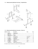
Page 33: ... JWL1221VSS 103 Cover 4 5 TS 0051021 Hex Cap Screw 5 16 18x5 8 8 6 Threaded Insert 3 8 16 14 7 TS 0060051 Hex Cap Screw 3 8 16x1 12 9 TS 0720091 Lock Washer 3 8 12 10 TS 0680042 Flat Washer 3 8 12 11 JWL1642 206 Leveler includes 12 4 12 TS 0570031 Hex Nut 3 8 16 4 13 TS 0720081 Lock Washer 5 16 8 14 TS 0680031 Flat Washer 5 16 14 1792014S HP Hardware package items with Some parts are shown for ref...

Page 34: ...n 1 2 TS 0209071 Socket Head Cap Screw 3 8 16x1 1 2 4 3 TS 0720091 Lock Washer 3 8 4 4 TS 0680042 Flat Washer 3 8 4 PM2014 ERPK Extension Toolrest Post Kit item 5 6 1 5 PM2014 305 Extension Toolrest Post 1 6 PM2014 306 Locking Handle 1 PM2014 TEA Toolrest Extension Assembly item 7 thru 10 7 PM2014 307 Toolrest Extension 1 8 JWL1440 206 Handle 1 9 JWL1440 207 Tool Rest Lock Bushing Set 1 10 TS 0570...

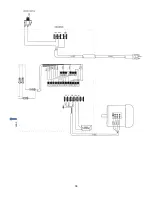
Page 35: ...35 16 0 Electrical connections PM2014 Lathe cont next page ...

Page 36: ...36 cont ...

Page 37: ...ires further inspection the Technical Service representative will explain and assist with any additional action needed Powermatic has Authorized Service Centers located throughout the United States For the name of an Authorized Service Center in your area call 1 800 274 6846 or use the Service Center Locator on the Powermatic website More Information Powermatic is constantly adding new products Fo...

Page 38: ...38 This page intentionally left blank ...

Page 39: ...39 This page intentionally left blank ...

Page 40: ...40 427 New Sanford Road LaVergne Tennessee 37086 Phone 800 274 6848 www powermatic com ...

Reviews: