8
ELECTRICAL CONNECTIONS
▲
WARNING: DO NOT APPLY POWER UNTIL TOLD TO DO SO!
RISK OF SHOCK OR INJURY MAY RESULT.
Before connecting the
operator, use a voltmeter to determine that the electrical service is 115
VAC. This operator cannot be connected to 220 volts. Damage will result,
which is NOT covered by warranty.
1.
▲
Be sure power switches at source and operator are OFF.
2.Connect incoming power lines and ground wire as follows:
Hot leg (black) to black; Neutral (white) to white; Ground to screw.
Note:
Wiring to operator must use watertight materials in accordance with
local electric code.
Note:
Master/Slave installation should have SEPARATE
power supply wiring. If sharing a power supply line,
obstruction sensing adjustments may require recalibration.
FOR MASTER/SLAVE INSTALLATION:
Note:
A single unit is considered Master.
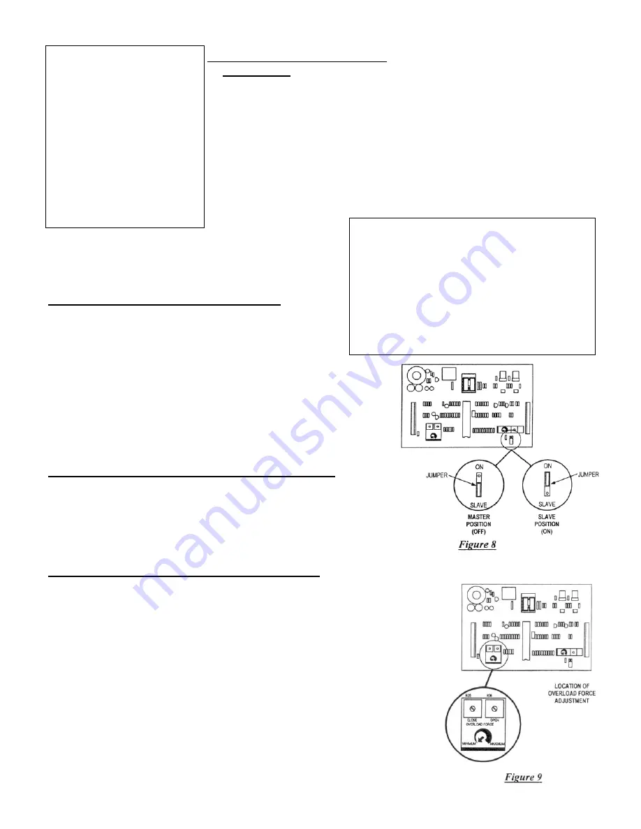
1. Place jumper on the master operator's P.C. board in the
"OFF" position (See Fig. 8).
2. Place jumper on slave operator's P.C. board in the
"ON" position. (See Fig. 8).
3. Connect terminal # 15 of Master unit to terminal #5 of slave unit.
4. Connect terminal # 16 of Master unit to terminal #6 of slave unit.
5. Connect Terminal # 17 of Master unit to terminal #7 of slave
unit. Note: In Master/Slave installation, one unit must be
converted to LEFT HAND operation.
CONNECTION OF A THREE BUTTON STATION:
Note: All control contacts must be NORMALLY OPEN.
Connect "STOP" button to terminal #4
Connect "COMMON" button to terminal #5
Connect "OPEN" button to terminal #6
Connect "CLOSE" to terminal #7
PRIMARY OBSTRUCTION SENSING DEVICE:
Note:
Gate must move smoothly and easily in manual operation before
attempting this adjustment. This unit is supplied with a current sensing
system which will stop gate when activated and then back the gate off
approximately 2 inches and stop. If the gate is started again and the sensing
system is activated a second time before hitting a limit switch, the gate will
stop and sound a warning signal. A constant pressure control will then be
needed to start the gate. This sensing system has adjustments located on
printed circuit board (See Fig. 9). The force required to activate the system
may be adjusted in both OPEN and CLOSE direction separately. Start at
minimum force, and increase force until it is just over what is required to
move the gate smoothly without any nuisance tripping.
NEVER INCREASE FORCE SETTING TO MAKE UP FOR A GATE
THAT IS NOT MAINTAINED PROPERLY. THIS WILL
DESENSITIZE THE OPERATION OF THE SAFETY SYSTEM.
HIGH VOLTAGE
WIRE GAUGE/
DISTANCE CHART
16 AWG
Up to 200’
14 AWG
200’ to 500’
12 AWG
500’ to 900’
10 AWG
900’ to 1200’
Over 1200’ consult the factory
HIGH VOLTAGE WIRE GAUGE/
DISTANCE CHART
24 AWG
Up to 150’
20 AWG
150’ to 250’
18 AWG
500’ to 900’
Control wiring should be run as twisted pairs. Do not run
control wires in the same conduit as power wires,
telephone wires or loop detectors leads
Summary of Contents for RSG 2000
Page 13: ...13...


