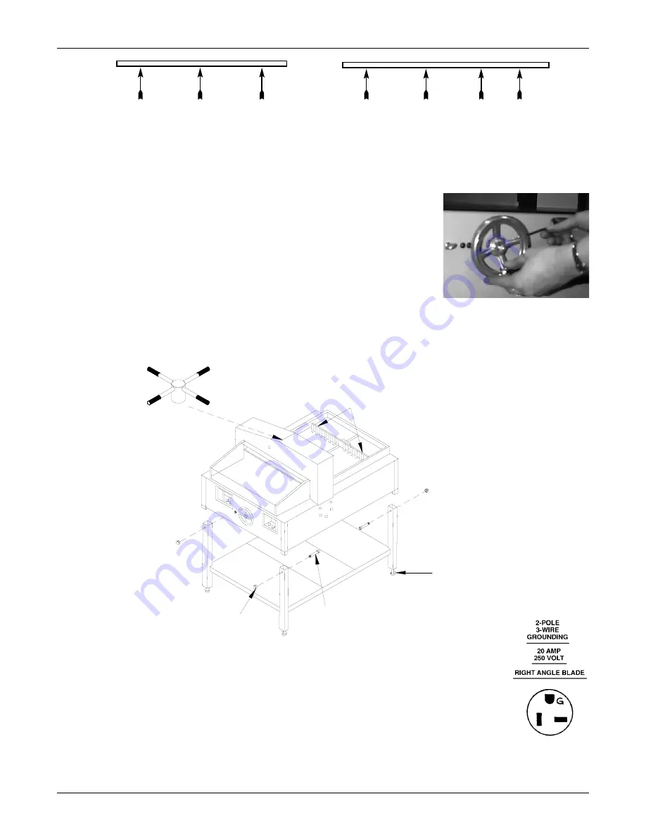
4.4 Installing the Handwheel
To help prevent shipping damage, the back gauge handwheel to your PowerLine cutter hasnot been installed. A 5/32" Hex
key wrench has been included so that the handwheel can be installed on the shaft that extends from the front center of the
machine. Two handwheel set screws must be securely tightened so that the handwheel will not freely turn on the shaft. To
install the handwheel:
1. Located the shaft that protrudes from the front center of the machine.
2. Slide the handwheel onto the shaft so that one of the set screws is aligned over the
flat surface on the shaft. Position the handwheel so that it will not rub against the
machine chassis. This is achieved when the end of the shaft is even with the outer
surface of the handwheel inner hub.
3. When the handwheel is properly positioned, securely tighten each set screw against
the shaft. You may use a commercial thread locking glue to secure the set screws in
place.
4.4 Separating the Stand and Chassis
To separate the chassis from the stand, remove the carriage bolt and acorn nut from the top of each stand leg. Lift the chas-
sis from the stand using a mechanical lifting device. To reassemble the stand and chassis, lower the chassis onto the stand
and install the carriage bolt and acorn nut through each stand leg.
4.5 Power Requirements
The electric cutter is equipped with a 20 Amp power plug (NEMA #6-20P). This cutter requires an 20
Amp circuit with a 20 Amp receptacle (NEMA #6-20R). Have a qualified electrician install the appro-
priate branch circuit and receptacle.
4.6 Optional Side Tables
To install the optional side tables, simply align the holes in the tables with the screw holes in the machine frame. Install and
tighten the provided screws.
PowerLine Operating Instructions
4
26" False Clamp Screw Location
21" False Clamp Screw Location
ACORN NUT (4)
CARRIAGE BOLT (4)
LEG LEVELER (4)
BACK GAUGE LOCKING SCREWS (2)


