20
Scroll Enclosure Air Compressors
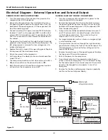
Electrical Diagram - External Operation and External Output
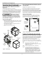
REMOTE ON / OFF SWITCH INSTRUCTIONS
1. Turn the compressor off and lockout the power to the
compressor per OSHA standards.
2. Remove the top panel from the scroll cabinet to access
the operating panel. Remove the plastic cover from the
backside of the operating panel. Lift the expansion PCB
from the operating panel.
3. Connect an external AC power source of 200 V between
terminals 1 and 2 on the expansion PCB. A switch rated
at least 200 V AC should be used. It is possible to use the
200 V AC source from the transformer on the bottom of
the cabinet.
4. The power wires should run through the right hand side
grommet when facing the front of the control panel. The
left side grommet is reserved for low voltage wires (to
reduce interference).
5. Replace the plastic cover of the operating panel. Replace
the top cover of the scroll compressor.
6. Return the power to the compressor.
7. Set the mode on the display to show external operation
mode (“ECon”).
8. The compressor should now start when external switch is
ON
, and turn off when the external switch is
OFF
.
9. Both the external switch and the control panel controls
will now turn the compressor on and off.
GENERAL FAULT DRY CONTACT CONNECTIONS
1. Turn the compressor off and lockout the power to the
compressor per OSHA standards.
2. Remove the top panel from the scroll cabinet to access
the operating panel. Remove the plastic cover from the
backside of the operating panel. Lift the expansion PCB
from the operating panel.
3. Output wires should be connected between terminals 3
and 4. The dry contacts are normally open; when there
is a fault, the contacts close. The contact rating is as
follows: 200 V AC, 1A, maximum.
4. For larger load devices such as a horn or emergency light,
a relay should be used.
5. The signal wires should run through the right hand side
grommet when facing the front of the control panel. The
left side grommet is reserved for low voltage wires (to
reduce interference).
6. Replace the plastic cover of the operating panel. Replace
the top cover of the scroll compressor.
7. Return the power to the compressor.
8. The external output will now operate when there is
either a caution or emergency. This is the default setting
for the control panel. The external output of the control
panel can be changed to only operate in case of an
emergency.
9. Reasons for Caution and Emergency stop are needed to
confi rm on the control panel display.
Self-holding
switch
AC200V
Electric source
External operation circuit
*See "ECon" in manual
External output circuit
for General Fault
Dry contact
(Normally open)
CN7
CN6
CN3
CN26
CN27
CN5
CN4
TB1
CN29
CN32
CN28
1
2
3
4
EXB
Expansion circuit board
Crimping terminal size
R1.25-3
CR 1
CN2
CN22
CN31
CN26
CN25
CN24
CN23
CN21
CN20
CN11
CN10
CN1
CN27
CN30
1A
CN13
F
DB
Display circuit board
CN1
MB
Main circuit board
Modular plug for
setting and communication
TRANS
CN12
Figure 15

