background image


16 

7.2 Button operation


Please note the five operating buttons on the front panel: 

1. “ON/OFF” 

button: 

(a)  Push “ON/OFF” button (at least 1 seconds) to turn on the UPS. 

(b)  When UPS is working, push the “ON/OFF” button(at least 2 seconds) to turn off 

the UPS. 

2. “STATUS” 

button: 


Use this button to check content of UPS and the method is listed


below: 

(a)  Push the “STATUS” button (at least 2 seconds) to check content of UPS. Each 

content can be displayed by pressing at once, and it has fifteen kinds of function 

to be checked. 

(b)  If no pressing within 10 seconds, it will return to original status. 

3. “FUNC” 

button: 

Each function can be enabled by pressing this button & “ENTER” button. 

(a)  Push the “FUNC ” button (at least 2 seconds) to choose which function that you 

want. Each content can be displayed by pressing at once, and it has fourteen 

kinds of function to be checked. 

(b)  After choosing the function, push the “ENTER” button to enter the function that 

you want. 

(c)  Push the “FUNC” button to choose other function again. 

(d)  Push the “ENTER” button to enable your function. 

(e)  Push the “ENTER” button to confirm and enable your function. 

(f)  If no pressing within 10 seconds, it will return to original status. 

4. “ENTER” 

button: 

Use this button to enter

enable or confirm the function that you want. 

5. “ESCAPE” 

button: 

Use this button to return to main display(Line mode or Battery Mode). 


17

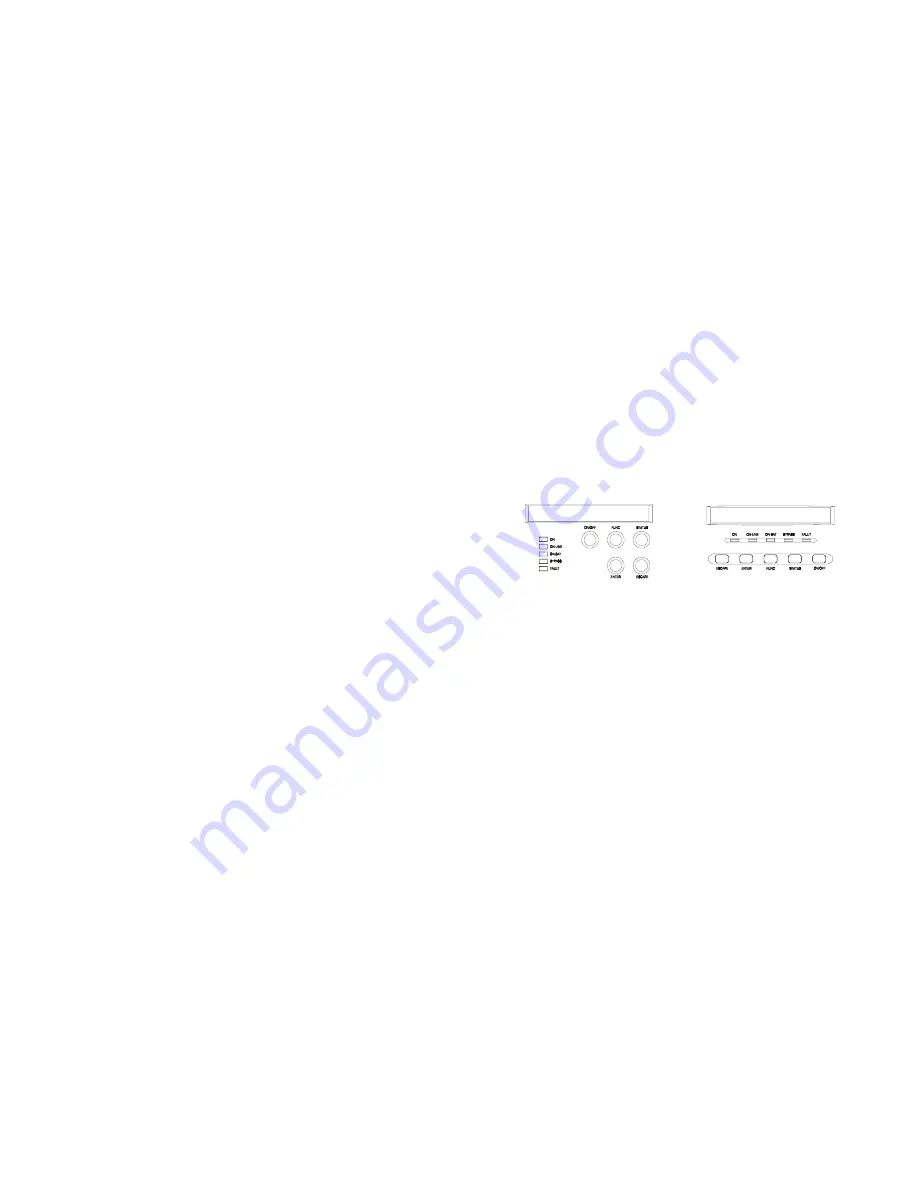
7.3 Control panel functions 

Operation of the UPS is indicated on the monitor panel with five LED indicators and an 
LCD screen. This display is also capable of alerting the user with audible alarms. 

ON

This green LED is lit when UPS has been turned on. 

ON-LINE

When the UPS is in normal or static bypass modes, there is voltage at the 

 output terminals and this LED will light up in green. 

ON-BAT

While operating in battery mode. 

BYPASS

While operating in bypass mode, this LED will light up in yellow. 

FAULT

If any internal error occurs in the UPS, this LED will light up in red and give off an 

audible alarm. Press any of the buttons on the front panel to turn off the alarm 

status of the UPS, measurements and alarms are all indicated on the LCD 
screen. 


Control panel 

Normal display 

The UPS status is shown in normal display mode. From here you have a choice to go to 
UPS meters display and the Setting display by pushing the button. 

Summary of Contents for 12K VA

Page 1: ...fluenced by harmful interference from the equipment it is recommended to use one of the following preventive measures Place the receiving antenna in a separate location or orientation Ensure a greater...

Page 2: ...servicing to qualified service personnel CAUTION Non isolated Battery supply Risk of electric shock battery circuit is not isolated from AC input hazardous voltage may exist between battery terminals...

Page 3: ...nstallation must be carried out in accordance with this manual Electrical installations must also carefully follow local legislation and regulations Only qualified personnel should conduct these insta...

Page 4: ...management system always monitors the conditions of the batteries sends any forewarnings if replacement is needed Otherwise every 30 days of normal mode operation a battery discharge test is performed...

Page 5: ...in this manual The greatest care possible must be taken for any of these operations and any change thereof may prove very hazardous to the operator 5 4 Storage 4 1 Storage Please adhere to the followi...

Page 6: ...ptions Avoid extremes of temperature and humidity Maximal battery life can be attained with a recommended temperature range of 15 C to 25 C Provide protection for the equipment from moisture Space and...

Page 7: ...8 5K 6KVA Rear panel With ISO 9 8K 12KVA Rear panel Without ISO...

Page 8: ...the installation site has all electrical connections properly carried out In addition refer to figures 2 and 3 to check the fuse and cable dimensions Isolate and secure the source against reclosing Bo...

Page 9: ...ters to select Default settings are as follows Settings Selection Factory default Output Voltage Setting 208 220 230 240 Vac 230V FOR HV series Input Bypass Voltage 10 10 15 15 20 10 15 Input Frequenc...

Page 10: ...RI Output 8 24 VDC Power Fig 5 Caution Max rated values 24Vdc 50mA 15 USB port option Connecting the UPS to your computer is accomplished through the USB port on the back of your computer USB complian...

Page 11: ...Push the ENTER button to confirm and enable your function f If no pressing within 10 seconds it will return to original status 4 ENTER button Use this button to enter enable or confirm the function t...

Page 12: ...CPU Version 19 UPS configurations 1 Various settings that have been chosen are shown in the UPS setting display 2 To enter configuration mode press the FUNC button for one second The first configurati...

Page 13: ...ed For UPS to predict Backup time 0 only internal batteries 1 one external cabinet 2 two external cabinets 0 Site wiring alarm Sit Fault Set You can enable or disable the site wiring alarm Enable Disa...

Page 14: ...ps The UPS is doing a battery test No action needed The UPS will return to normal operation when it successfully completes the battery test Over Charge Constant beep Batteries are overcharged Turn off...

Page 15: ...al and workmanship for a period of 24 months from its original date of purchase 25 10 Technical Specifications GENERAL Rated power 5000VA 6000 VA 8000 VA 10000 VA 12000VA at p f 0 7 Technology On line...

Page 16: ...mber of batteries 20 20 20 20 40 Backup time full load 7 min 6 min 5 min 6 min 6min Recharge time 8 hours to 90 8 hours to 90 8 hours to 90 8 hours to 90 8 hours to 90 Without ISOTR 280x580x570 280x58...

Page 17: ...28 MAINTENANCE SWITCH NORMAL BY PASS 1 2 INV MAIN INV MAIN or...

Reviews: