background image


13 

5.4 

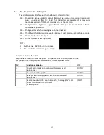
The pin of computer interface port: 


  The pin of computer interface port has the following characteristics: 

5.4.1.  Pin 6 and 8 are open collector outputs that must be pulled up to a common referenced 

supply  no  greater  than  DC  +40V.  The  transistors  are  capable  of  a  maximum 
nonconductive load of DC 25 mA, Use only pin 5 as the common. 

5.4.2.  Pin 8 generates a high to Low signal when the battery inside the UPS has less than 2 

minutes back up time left. 

5.4.3.  Pin 6 generates a high to Low signal when the line is fail. 
5.4.4.  The UPS will shut down when a high RS-232 level is sustained on pin 3 for 0.36 seconds. 
5.4.5.  Pin 2 is the RS-232 data output. 
5.4.6.  Pin 3 is also RS-232 data input (RxD) 
 
NOTE: 
1.


Switch 40V, 0.25A non-inductive. 

2.


Pin 5 should be connected to ground only. 


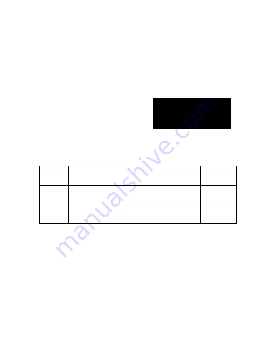
Communicating Interface Port 
We  provide  a  standard RS232  line  (that  is  compatible  with  DB9  line)  socket  on the 
rear panel of UPS. That port possesses several signals as explained below: 


Pin# 

Function Explanation 

I/O 

Power Fail-normally open status, will become closed 
during active 

OUTPUT 

Reference GND for pin6,8 

OUTPUT 

Battery Low- normally open status, will become closed 
during active 

OUTPUT 

Remote shutdown UPS-keep this pin at high v5V~+12V) 
500ms to shutdown UPS. Activates 
at battery mode 

INPUT 


Summary of Contents for 1000AP

Page 1: ...U P S Line Interactive Sine Wave 1000VA 3000VA USER S MANUAL...

Page 2: ...ore CAUTION Do not open or mutilate the battery released electrolyte is harmful to the skin and eyes CAUTION A battery can present a risk of electric shock and high short circuit current The following...

Page 3: ...le of contents 3 Save these instructions 4 1 Presentation 5 2 Installation 8 3 Operation 10 4 Alarm 11 5 Software and Interface Port 12 6 Maintenance and Storage 14 7 Battery and Battery Cabinet 14 Ap...

Page 4: ...it can provide immediately backup power from the batteries without any interruption Complete transference will be achieved within 4m seconds with no interruption Beside this when the utility power is...

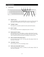
Page 5: ...TTERY indicator The LED illuminates when the UPS s battery is no longer useful and must be replaced Note When replace battery disconnect the utility power then open the case and take notice of the bat...

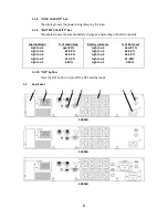
Page 6: ...ttery capacity 1 1 10 OFF button Press the OFF button to turn off the UPS and the loads 1 2 Rear Panel 7 2 1 8 6 3 4 5 1000VA 1500VA 2000VA Load Indicator Light no 5 Light no 4 Light no 3 Light no 2 L...

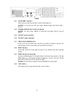
Page 7: ...the connected loads exceed the protected receptacle s capacity The center plungers of the circuit breakers fuse extend when tripped 1 2 6 RS232 interface Provide both RS 232 and relay signal to suppo...

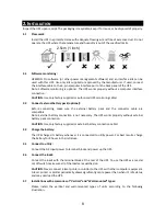
Page 8: ...ttery pack and the connector cable are compatible Note External battery connection is not necessary The UPS works properly without external battery pack connection CAUTION Use only factory supplied or...

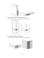
Page 9: ...essories of Rack mounted types Please install the types of units according to the following illustration 2 9 Installation with accessories of Stack types Please install the types of units according to...

Page 10: ...erating 3 4 Self test Use the self test to verify both the operation of the UPS and the condition of the battery In normal utility power push the ON TEST button more than 1 second and UPS performs a s...

Page 11: ...with memory module The UPS will automatically memorize Green Mode status when switched off If no manual operation to enable or disable the Green Mode at the time when UPS is switched on the Green Mode...

Page 12: ...ur dealer for more information on computer OS compatible solutions 5 2 Interface Kits A series of interface kits is available for operation systems that provide UPS monitoring Each interface kit inclu...

Page 13: ...wn when a high RS 232 level is sustained on pin 3 for 0 36 seconds 5 4 5 Pin 2 is the RS 232 data output 5 4 6 Pin 3 is also RS 232 data input RxD NOTE 1 Switch rating 40V 0 25A non inductive 2 Pin 5...

Page 14: ...cted to the computer interface port to avoid unnecessary draining the battery 6 3 To extend the storage 6 3 1 During the environment where the ambient temperature is 15 to 30 5 to 86 charge the UPS s...

Page 15: ...ault Contact the dealer or service center for help Buzzer keeps beeping Overload Take off some load Utility Indicating light is shining There is an open circuit on UPS input protector Move the Input N...

Page 16: ...300Joules 2ms Short circuit UPS output cut off immediately or protected by input circuit breaker Tele communication RJ45 x2 EMI RFI filter 100kHz to 10MHz Fuse Yes Alarm Buzzer beeps under backup mod...

Reviews: