


26
PowerBox-Systems
− World Leaders in RC Power Supply Systems
•
Number of wheel doors
Enter the number of doors. If all the wheel doors are to be operated by a
single val-
ve, enter a
1
at
Number of front doors
, and leave the
Number of rear doors
vacant.
•
Pause between undercarriage and doors
Extend:
The time the system waits after extending the undercarriage before the
wheel doors close. Applies to modes 2 and 3
only.
Retract:
The time the system waits after retracting the undercarriage before the
wheel doors close. Applies to all
modes.
Once you have completed all these settings, select
Continue
.
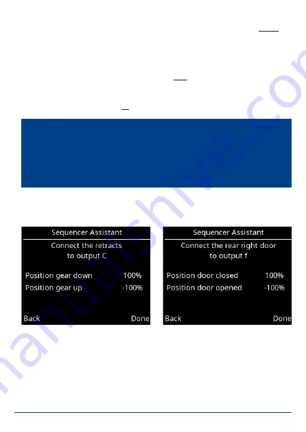
The positions of the undercarriage control system and all the wheel doors are
now set up in accordance with the number of wheel doors you have entered. At
this point you should connect the retract control unit and the wheel doors to the
appropriate output of the
Royal SR2
. Starting with
A
the Assistant searches for
outputs which have no special functions – i.e.
Direct xy
outputs, which are not
assigned to a gyro or other sequencer function.
Note:
All settings in the Assistant are stored – including all subsequent servo
positions. For example, if you wish to change the retract mode or the pause
period after completing the Assistant, simply run through the Assistant again
without changing the positions. The Assistant then simply adjusts the timed
sequence.


