background image


b)


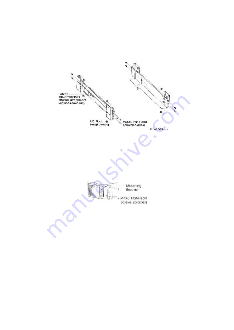
Select the proper size in the rack for positioning the UPS (see Figure 2). The 

railoccupies four positions on the front and rear of the rack. 

c)


Tighten four M5 Umbrella Nuts in the side of rail assembly(see Figure 1). 

d)


Fix one rail assembly to the front of the rack with one M5×12 pan-head screw and 
one M5 cage nut. Using two M5 cage nuts and two M5×12 pan-head screws, to fix 

the rail assembly to the rear of the rack. 


Figure2 Fixing the Rails 

e)


Repeat Steps 3 and 4 for the other rail assembly. 

f)


Tighten the four butterfly nuts in the middle of each rail assembly. 

g)


If installing optional cabinets, repeat Step 1 through Step 6 for each rail kit. 

h)


Place the UPS on a flat, stable surface with the front of the cabinet facing to you. 

i)


Align the mounting brackets with the screw holes on each side of the UPS and fix 

with the supplied M4×8 flat-head screws(see Figure 3) 


Figure3Installing the Mounting Brackets 

j)


If installing optional cabinets, repeat Step 8 and 9 for each cabinet. 

k)


Slide the UPS and any other optional cabinets into the rack. 

l)


Secure the front of the UPS to the rack using one M5×12 pan-head screws and one 

M5 cage nuts on each side(see Figure 4).Install the bottom screw on each side 

through the bottom hole of mounting bracket and the bottom hole of the rail. 

Repeat for any optional cabinets. 

Summary of Contents for Powerpure RT 1

Page 1: ...PS designed by ourteam of UPS experts With excellent electrical performance advanced intelligent monitoring and network functionsas well as complying with EMC and safety standards make the PowerPure RT series one of the leading UPS in the industry Read this manual carefully before installation This manual provides technical support to the operator of the equipment ...

Page 2: ...on and setup 4 2 1 Unpack checking 4 2 2 Real panel view 5 2 3 Installing the UPS 6 2 4 UPS start up and turn off 15 2 5 Configuring Battery Setings 15 3 Operations 20 3 1 Button operation 20 3 2 Setup the UPS 20 3 3 LCD display 22 3 4 UPS setting 24 3 5 Operational Status and Mode s 26 3 6 Alarm or Fault reference code 27 4 Troubleshooting 27 5 Storage and Maintenance 30 6 Options 30 7 Specificat...

Page 3: ...ay occur if the UPS system is moved directly from cold to warm environment The UPS system must be absolutely dry before being installed Please allow at least two hours for the UPS system to acclimate the environment Do not install the UPS system near water or in moist environments Do not install the UPS system where it would be exposed to direct sunlight or near heater Do not block ventilation hol...

Page 4: ...ted to the battery and electrically live and dangerous Before carrying out any kind of service and or maintenance disconnect the batteries and verify that no current is present and no hazardous voltage exists in the terminals of high capability capacitor such as BUS capacitors Only persons are adequately familiar with batteries and with the required precautionary measures may replace batteries and...

Page 5: ...e the package is damaged Please keep the original package in a safe place for future use 2 1 Unpack checking Don t lean the UPS when moving it out from the packaging Check the appearance to see if the UPS is damaged or not during the transportation do not switch on the UPS if any damage found Please contact the dealer right away Check the accessories according to the packing list and contact the d...

Page 6: ...5 2 2 Real panel view 1KVA S H 2KVA S H 3KVA S H 1 Output receptacles 10A 2 Battery Terminal ...

Page 7: ... in 19 racks with a distance from front to rear around 70 76 cm 27 to 30 inches deep CAUTION The cabinet is heavy Removing the cabinet from its carton requires a minimum of two people If installing optional EBP S make sure to install the EBP S directlybelow the UPS so that all wiring between the cabinets is installed behind the front covers and inaccessible to users NOTEMounting rails are required...

Page 8: ...l assembly g If installing optional cabinets repeat Step 1 through Step 6 for each rail kit h Place the UPS on a flat stable surface with the front of the cabinet facing to you i Align the mounting brackets with the screw holes on each side of the UPS and fix with the supplied M4 8 flat head screws see Figure 3 Figure3Installing the Mounting Brackets j If installing optional cabinets repeat Step 8...

Page 9: ...e damage may occur to your equipment and void your warranty NOTE Do not connect the ups power cord to utility until after installation is completed a Remove the front cover of each UPS Press the cover side with LCD display hold the other side and quickly extract it then extract the other side with display see Fig 5 NOTE A ribbon cable connects the LCD control cover to the UPS Do not pull on the ca...

Page 10: ...ction c If you are installing EBPS see the following section Connectingthe EBP s before continuing with the UPS installation Figure6Connecting the UPS Internal Batteries d Replace the UPS front cover To replace the cover verify that the ribbon cable is protected and ifEBPS are installed the EBP cable is routed through the knockouton the bottom of the cover Put the front cover hooks of side with di...

Page 11: ...e ground bonding screw for each model g If an emergency power off disconnect switch is required by localcodes see Remote Emergency Power off REPO to install the REPO switch before powering onthe UPS h Continue to UPS Startup Connecting the EBP s 1 To install the optional EBP s for a UPS a Remove the front cover of each EBP and UPS see Figure 8 It is the same with the installation of the front cove...

Page 12: ...e Plug the EBP cable s into the battery connector s as shown inFigure 10 Up to four EBPS may be connected to the UPS Connect black to black Press the connector tightly together to ensure a properconnection To connect a second EBP unclip the EBP connector onthe first EBP and pull gently to extend the wiring to the EBPconnector on the second EBP Repeat for any additional EBPs f Verify that the EBP c...

Page 13: ...e UPS installation Rackmountconverted to Tower Installation 1 Rackmountconverted to Tower plasticbase installation Two plastic base brackets Flatten it after intercrossing Intercross as following Figure Figure 11 plasticbase installation If anEBP is needed to be placed in the middle the assembly of plastic base is similar Figure 11 The difference is that two 1U plastic base extended boards are add...

Page 14: ...2 increase EBP plasticbase installation 2 Rackmountconverted to TowerLCD Displayplasticbase installation A B C Figure 13increase UPSplasticbase installation The installation between UPS and EBPS can be referred to Fig 14 ...

Page 15: ...14 Figure14 The installation for UPS and battery boxs Figure15 Long backup external battery connection a Install the base then place the RT UPS on the base one by one as Fig 13 shows ...

Page 16: ...PS is working in line mode 2 Turn on the UPS by DC without mains power a When mains power is disconnected press and hold the ON key for more than half a second to start UPS b The operation of the UPS in the process of start is almost the same as that when mains power is in After finishing the self test the corresponding LED lights and the UPS is working in battery mode Turn off operation 1 Turn of...

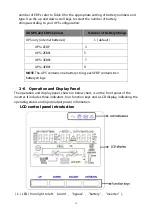
Page 17: ...w chart is on the front panel of the inverter It includes three indicators four function keys and a LCD display indicating the operating status and input output power information LCD control panel introduction 1 LED fromright to left alarm bypass battery inverter All UPS and EBP Cabinets Number of BatteryStrings UPS only internal batteries 1 default UPS 1EBP 3 UPS 2EBPs 5 UPS 3EBPs 7 UPS 4EBPs 9 N...

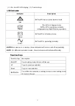
Page 18: ... in Battery mode Green OnThe UPS is operating normally NOTE When power on or startup these indicators will turn on and off sequentially NOTE On different operation modes these indicators will indicate differently Function Keys Function Key Description ESC OFF To exit setting mode Or turn off the ups UP To go to previous selection Down To go to next selection ENTER ON To confirm the selection in se...

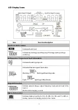
Page 19: ... Fault Information Indicatesthesettingprograms Indicatesthewarningand faultcodes Warning flashingwithwarningcode Fault lighting withfaultcode OutputInformation Indicate output voltage output frequency load percent load in VA load in Watt and discharging current Battery Information Indicates battery level by 0 24 25 49 50 74 and 75 100 in battery mode and charging status in line mode ...

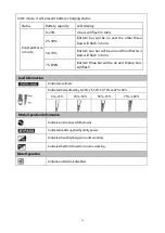
Page 20: ... on and the other two bars will flash in turns 75 100 Bottom three bar will be on and thetop bars will flash Load Information Indicatesoverload Indicatestheloadlevelby 0 24 25 50 50 74 and75 100 0 25 25 50 50 75 75 100 Mode Operation Information Indicatesunitconnectstothemains Indicatesloadissuppliedbyutilitypower Indicatestheutilitychargercircuitis working IndicatestheDC ACinvertercircuitis worki...

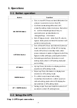
Page 21: ... and hold this button at least 2 seconds to turn off the UPS in battery mode UPS will be in standby mode under power normal or transfer to Bypass mode if the Bypass enable setting by pressing this button Exit setting mode Press this button to exit setting mode when in UPS setting mode but save nothing UP Button Up key Press this button to display previous selection in UPS setting mode DOWN Button ...

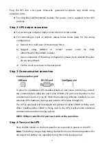
Page 22: ...mmunication connection Communication port To allow for unattended UPS shutdown start up and status monitoring connect the communication cable one end to the USB RS 232 port and the other to the communication port of your PC With the monitoring software installed you can schedule UPS shutdown start up and monitor UPS status through PC The UPS is equipped with intelligent slot perfect for either SNM...

Page 23: ...own You may insert provided CD into CD ROM to install the monitoring software 3 3 LCD display Part one Rack display There are 9 interfaces available in the LCD display Item Interface Description Content Displayed 01 Input voltage Output voltage 02 Battery voltage Backup time Batterycapacity 03 Input frequency Output frequency ...

Page 24: ...23 04 Load 05 Environment Temperature 06 UPS model 07 Firmware Version 08 Alarm Code Warming Message All alarm codes are present when abnormal behavior s occur s ...

Page 25: ...Exit setting mode After the UPS turn ON press buttons UP Down for 5seconds and then goes into the setting interface page Note Press Down button to confirm selection and exit setting mode when LCD display the last selection in UPS setting mode Item Settings Content display 01 Mode setting Press Enter button to change the setting ECO or NORor CF Press UP button to select the previous setting Press D...

Page 26: ...voltae setting Once Press Enter button to change the setting 1 75 1 84 1 92 Press UP button to select the previous setting Press DOWN button to select the next setting 06 Battery EOD voltae setting Second Press Enter button to change the setting 1 60 1 70 1 75 1 80 Press UP button to select the previous setting Press DOWN button to select the next setting 07 Bypass voltage upper limit setting Pres...

Page 27: ...to select the previous setting Press DOWN button to save and exit the setup 10 BYPASS enable disable setting Press Enter button to change thesetting ON or OFF Press UP button to select the previous setting Press DOWN button to save and exit the setup 3 5 Operational Status and Mode s item Content Displayed 1 Initialized 2 Standby Mode 3 No Output 4 Bypass Mode 5 Utility Mode 6 Battery Mode 7 Batte...

Page 28: ...ent Once per second BPS LED blinking 32 Overload Once per second INV or BPS LED blinking 33 No battery Once per second Battery LED blinking 34 Battery under voltage Once per second Battery LED blinking 35 Battery low pre warning Once per second Battery LED blinking 36 Over load time out Once per 2 seconds Fault LED blinking 37 DC component over limit Once per 2 seconds INV LED blinking 39 Mains vo...

Page 29: ... output Alarm code is shown as 29 and FAULT led light The UPS shut down automatically because short circuit occurs on the UPS output Check output wiring and if connected devices are in short circuit status Alarm code is shown as 9 and FAULT led light Fan fault Contact your dealer Alarm code is shown as 01 02 15 16 17 18 A UPS internal fault has occurred Contact your dealer Battery backup time is s...

Page 30: ...nformation Check UPS output voltage BUS voltage End Check sps 12V Bat voltage Replace power board Replace control panel No No Fan issue LCD issue Replace fan Replace control panel Yes Yes No Replace control panel UPS Fault no output Rfer to alarm Fault code reference No Replace power board No Yes Replace control panel No Replace control panel No Yes UPS No output Replace power board No Yes Replace...

Page 31: ...MP Loosen the 2 torquescrews on each side of thecard Carefully insert the SNMP card and lock the screws Theslotcalled SNMP supportstheMEGAtec protocol Weadvise thatNetAgentII 3 port is also a tooltoremotelymonitorandmanageanyUPS system NetAgentII 3Portssupportsthe ModemDial in PPP functiontoenabletheremotecontrol via the internetwhen thenetworkisunavailable In additiontothefeaturesofa standard Net...

Page 32: ...l monitoring devices via terminal boardtofacilitatethe effective monitoring ofthereal timestatusofUPS andtimely feedback thestatusto monitorwhen abnormal situation occurs suchas UPSfailure mains interruption UPS bypassand ect Itis installed in theintelligent slotofthe UPS Therelaycard includes6 outputportsandone inputport Pleaserefer tothefollowingtable fordetail Pins definition of connecting term...

Page 33: ...transfer 300Vac 5 High line comeback 290Vac 5 Operating frequency range 40 70Hz Power factor 0 99 100 load Nominal Input Voltage Bypass voltage range Bypass high voltage point 230 264 setting the high voltage point in LCD from 230Vac to 264Vac Default 264Vac Bypass low voltage point 170 220 setting the low voltage point in LCD from 170Vac to 220Vac Default 170Vac Generator input Support OUTPUT Out...

Page 34: ...ter 5 seconds when the utility is normal 150 UPS transfer to bypass immediately when the utility is normal 35 Ambient Temp 40 105 110 UPS transfer to bypass after 1minute when the utility is normal 110 130 UPS transfer to bypass after 5 seconds when the utility is normal 130 UPS transfer to bypass immediately when the utility is normal Short Circuit Hold Whole System Overheat Line Mode Switch to B...

Page 35: ...34 Product specifications are subject to change without further notice ...

Reviews: