background image

Operation and installation manual 

Page 56 of 96 

(PVI-STRINGCOMB (-S, -MC, -S-MC) - Rev:1.0) 


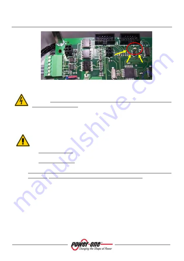
Figure 9-21: LED indicating normal operation 


Replace  the  Plexiglas  panel  on  the  negative  side  using  the  specific 
screws,  paying  particular  attention  not  to  accidentally  touch  the 
exposed electrical parts. 


9.3.14  Connection of Strings [over 10 strings] 


If more than 10 strings must be connected, they must be connected in 
parallel,  two  by  two,  according  to  the  following  logical  sequence,  for 
example: 

For positive poles: (S1+, S2+ with F1), (S3+, S4+ with F2), 

…..,(S19+, S20+ with F10) 

For negative poles: (S1-, S2- with F11), (S3-, S4- with F12), ….., 

(S19-, S20- with F20) 

To connect the strings, both positive and negative poles, the instructions 
in §9.3.12 and 9.3.13 respectively must be strictly followed. 
In this case, the cable glands to be used must be positioned on the side 
flanges (Figure 4-3) 
 

9.3.15  Setting the DC switch (only version –S) 

If  there  is  a  switch/isolator  (PVI-STRINGCOMB-S),  it  must  be  opened, 
turning it to position 0 (green window). 


Summary of Contents for AURORA PVI-STRINGCOMB

Page 1: ...AURORA BOXES FOR THE CONNECTION OF STRINGS FOR PHOTOVOLTAIC APPLICATIONS INSTALLATION AND INSTRUCTION MANUAL Models PVI STRINGCOMB PVI STRINGCOMB S PVI STRINGCOMB MC PVI STRINGCOMB S MC Rev 1 0...

Page 2: ...n Author Date Approved by Change Description 0 0 A Morucci S Soldani 04 09 09 D Nocentini New StringComb 3L11 1 0 A Morucci S Soldani 14 10 09 D Nocentini New StringComb 3L11 POWER ONE Complete or par...

Page 3: ...15 3 1 WHY USE PVI STRINGCOMB S 15 4 FIELD OF APPLICATION AND GENERAL DESCRIPTION OF THE PARALLEL STRING PANEL PSP 18 5 ESSENTIAL INFORMATION FOR SAFETY 23 5 1 INTRODUCTION 23 5 2 OVERVIEW 24 6 DESCR...

Page 4: ...9 3 11 2 Connection of the negative output wire 53 9 3 12 Connection of the positive pole of the strings for max 10 strings 53 9 3 13 Connection of the Negative poles of the strings for max 10 strings...

Page 5: ...ER 71 12 5 1 S Comb Baud Rate Setting 72 12 6 PVI STRINGCOMB MONITORING GLOBAL 73 12 7 PVI STRINGCOMB MONITORING SINGLE 74 12 8 DETAIL OF CONFIGURATION SUB MENU 78 12 8 1 Configuration Alarm Parameter...

Page 6: ...RIAL ZONE 31 FIGURE 7 1 MODALITY FOR THE PASSAGE OF THE SERIAL WIRE 32 FIGURE 7 2 TYPE OF CONNECTION FOR THE PVI STRINGCOMB S 33 FIGURE 7 3 CONNECTION METHODS 34 FIGURE 9 1 EXAMPLE OF BOX POSITION 37...

Page 7: ...T100 83 FIGURE 12 7 AUXILIARY INPUTS MONITORING IN2 GENERIC IN2 PT100 84 FIGURE 12 8 S4 SWITCH TO ENABLE ISOLATING SWITCH STATUS CHECK 85 FIGURE 12 9 DIGITAL INPUTS MONITORING ID1 GENERIC ID1 DCSWITCH...

Page 8: ...and the fuses the supplier must be contacted Power One shall accept no responsibility for damages consequent to the use of unsuitable spare parts Power One reserves the right to make any amendments to...

Page 9: ...el affixed to the PVI STRINGCOMB S contains the following information 1 Power One product s production code 2 Model name 3 Serial number 4 Week Year of production 5 Serial address RS485 6 Product revi...

Page 10: ...o understand and to carry out in order to avoid potential malfunctioning of the device or damage to the same and to property in general DANGER Paragraphs marked by this symbol contain specific indicat...

Page 11: ...regard the safety devices provided Make sure that you have read and fully understand the labels before installing the device The symbols used on the device referring to electrical parts are the follo...

Page 12: ...ental protection since the solar radiation which we receive from the sun is directly transformed into electricity without any combustion process and without the production of polluting waste The photo...

Page 13: ...ble These costs are mainly related to the wiring operations on inverter DC side and the consequent distribution on the AC side A photovoltaic panel is composed of many photovoltaic cells assembled on...

Page 14: ...d see APPENDIXES The current of each array must also be within the limits of the inverter downstream There are several factors and considerations to be taken into account when designing a photovoltaic...

Page 15: ...e string with the lower voltage i e made up of a lower number of modules connected in series Contrary to popular opinion shading has no significant influence on this effect this is because Bypass diod...

Page 16: ...aic modules generally show the Max Fuse Rating i e the maximum fuse rating that can be adopted to protect the panel string Usually the Max Fuse Rating is double of the module s short circuit current T...

Page 17: ...S MC S MC Rev 1 0 Figure 3 2 Intervention of protective fuse With PVI STRINGCOMB S the connected strings are protected and controlled In addition information on the string currents and other informati...

Page 18: ...strings allowing for protection in the case of breakdown Besides connecting the strings they allow the electrical quantities and other type of quantities for the entire photovoltaic field to be monit...

Page 19: ...string group concerned from the inverter downstream remote disconnection control and an auxiliary contact for displaying the switch status Every device features one input for resistance PT100 analogu...

Page 20: ...configuration model that can be found on the internet at the following address www stringcombconfigurator com String combs can be configured in different ways according to Number of strings that can b...

Page 21: ...Operation and installation manual Page 21 of 96 PVI STRINGCOMB S MC S MC Rev 1 0 Figure 4 2 Example of a photovoltaic system...

Page 22: ...puts accessories A POSITIVE STRING INPUT B NEGATIVE STRING INPUT C POSITIVE STRING OUTPUT D NEGATIVE STRING OUTPUT E CABLE GLAND FOR THE GROUND CABLE F INPUT OUTPUT FOR THE SIGNALS COMING FROM THE ENV...

Page 23: ...tremely important and necessary to disconnect the inverter before connecting the PVI STRINGCOMB S to the photovoltaic field installation and maintenance by means of the DC switches inside the inverter...

Page 24: ...onment where there is a risk of fire or explosion It is important that the qualified and suitably trained persons referred to in basic safety information are expert in the assembly installation and fu...

Page 25: ...Connection of signal input output and RS485 communication D Connection of the Earth wire Appendix A Technical Data E Connections for the output wires of the strings in parallel Positive and Negative F...

Page 26: ...Operation and installation manual Page 26 of 96 PVI STRINGCOMB S MC S MC Rev 1 0 Figure 6 2 Inside the PVI STRINGCOMB S...

Page 27: ...Operation and installation manual Page 27 of 96 PVI STRINGCOMB S MC S MC Rev 1 0 6 2 Operation diagram Figure 6 3 Indicative electrical diagram of the PVI STRINGCOMB S...

Page 28: ...hrough each channel is detected using special sensors these sensors are only installed on board A The status of every fuse positioned to protect each string Fuse Status is also checked The system also...

Page 29: ...al board for the connection of the analogue inputs 6 3 3 Overvoltage protection DC side The PVI STRINGCOMB S features a built in device for overvoltage protection with protection fuses Figure 6 2 item...

Page 30: ...t operation of this component 6 3 5 DC isolating switch Ref 6 1 item G Figure 6 1 PVI STRINGCOMB S only version S is fitted with a DC isolating switch in class DC21A The isolating switch fully disconn...

Page 31: ...on The control board fits a microcontroller that manages all signals detected in order to display them via the monitoring software The same data is then transmitted outside through the serial communic...

Page 32: ...erter and the PVI STRINGCOMB S must be made as indicated in Figure 7 1 and Figure 7 2 Termination of the line is already provided for inside the inverter 120 ohm The last PVI STRINGCOMB S must be term...

Page 33: ...Operation and installation manual Page 33 of 96 PVI STRINGCOMB S MC S MC Rev 1 0 Figure 7 2 Type of connection for the PVI STRINGCOMB S...

Page 34: ...only by means of the AURORA inverter The Computer must be connected to the RS485 of the inverter In this case the software used to monitor the PVI STRINGCOMB S is that of the Aurora inverter B This c...

Page 35: ...Since there are electronic circuits and electric connections inside the container care must be taken to avoid falls or blows which could later endanger regular operation of the device and people s sa...

Page 36: ...ranteed The environmental situation and positioning can influence the operation of the PVI STRINGCOMB S therefore the indications below must be followed 9 1 Place of installation With regard to the pl...

Page 37: ...al There must be no inflammable material in the vicinity and if the device is positioned indoors it is advisable to install a smoke detecting device When drawing up the project for the system the data...

Page 38: ...s It is therefore necessary to provide for a system to support the weight of the wires The figures below also show the position of the mounting holes and a possible solution for supporting the wires s...

Page 39: ...Operation and installation manual Page 39 of 96 PVI STRINGCOMB S MC S MC Rev 1 0 Figure 9 3 Complete use of the PVI STRINGCOMB S 20 strings...

Page 40: ...emoval of the Plexiglas guards Now connect all signals listed below items 1 to 10 since at this stage the device is not connected to the photovoltaic field 9 3 1 Removal of the guards Remove the Plexi...

Page 41: ...n Table 9 1 given below If the device is the last of the chain there will be only 3 wires If the device is the last of the chain the termination resistance must be enabled by the special micro switch...

Page 42: ...used for connecting the RS485 line shall be fitted with a wire terminal Figure 9 6 and grounded at one single point of the system Figure 9 7 Micro switch for RS485 line termination Also see Chapter 7...

Page 43: ...J11 7 9 8 X12 Table 9 2 Table of analogue inputs connection Table 9 2 lists the signals 0 10V with the corresponding indication on the monitoring software Ref 12 8 3 The AUX_IN_2 input 4 can be disab...

Page 44: ...sensors other than the indicated ones as far as they output a signal voltage of 0 10V Ref Appendix A Technical Data 9 3 4 PT100 Input Figure 9 9 Terminals for PT100 sensor connection Table 9 3 Table...

Page 45: ...ween the terminals 7 8 of the Terminal Block A Figure 9 11 Connect the antitheft system input wire as shown in Figure 9 10 Figure 9 11 Table 9 4 The alarm wire a normal wire is not supplied as standar...

Page 46: ...antitheft system alarm connection Please refer to software section Ref 11 12 12 7 item 3 for alarm management options Alarm signal can be remotely controlled not only via the monitoring software but a...

Page 47: ...any power supply Short circuit or open signals DIG1 and DIG1 or DIG2 and DIG2 to detect the status of an auxiliary contact through the monitoring interface Ref 11 12 7 12 8 4 DIG1 can also be used to...

Page 48: ...ote disconnection module allows you to trigger the DC isolating switch that can be manually reset To open the isolating switch a 24VAC or DC voltage shall be applied to the terminals indicated in Figu...

Page 49: ...is not usually operating at night PVI STRINGCOMB can be kept active at night using an insulated external power supply 24Vdc Ref Appendix A Technical Data In this way any antitheft monitoring and seri...

Page 50: ...I STRINGCOMB S MC S MC Rev 1 0 When an external 24VDC power supply is used set S3 switch in Figure 9 15 to ON EXT position Figure 9 15 External 24VDC supply switch If no external power supply is used...

Page 51: ...itch auxiliary status contact Figure 9 16 Isolating switch status connector The DC isolating switch status can be remotely checked through the auxiliary contact Figure 6 6 Ref Appendix A Technical Dat...

Page 52: ...e switches isolators of the DC voltage are OFF in the inverter B The wires coming from the inverter are not live check directly with a voltage meter 9 3 11 1 Connection of the positive output wire Aft...

Page 53: ...connected to the terminal board indicated by the label STRING POSITIVE Figure 9 18 Cable gland for positive strings connection Insert the special screwdriver Figure 9 19 into the clamp pushing it hom...

Page 54: ...PVI STRINGCOMB S MC S MC Rev 1 0 Figure 9 19 Use the special screwdriver on the terminals Replace the Plexiglas panel on the positive side using the specific screws paying particular attention not to...

Page 55: ...le coming from the string through the cable gland provided Figure 9 20 and connect it individually to the terminal Then remove the screwdriver and pull on the wire to check that it is correctly insert...

Page 56: ...nected in parallel two by two according to the following logical sequence for example For positive poles S1 S2 with F1 S3 S4 with F2 S19 S20 with F10 For negative poles S1 S2 with F11 S3 S4 with F12 S...

Page 57: ...is disconnected D Take note of the Serial Number S N given on the label affixed to the external surface Figure 1 1 9 3 19 Closing the cover Place the cover on the base and tighten all the 8 screws usi...

Page 58: ...of application specified No routine maintenance operations are envisaged whereas unscheduled maintenance interventions are not generally predictable and are due to verify the installation to disconnec...

Page 59: ...lained under paragraph 9 3 13 6 Before proceeding with the next step make sure that the DC output wire is not under voltage using a voltage meter 9 3 11 point B 7 Disconnect the and output wires from...

Page 60: ...in points 1 2 and 3 of Paragraph 10 1 1 1 Referring to points 4 and 5 of 10 1 1 for positive and negative strings respectively insert a suitable screwdriver Figure 9 19 fully home in the terminal so a...

Page 61: ...n for any other damaged cartridges 5 Check if present the fuses on the sides of the discharger These should be replaced if they are opened 6 Check by means of the monitoring software and according to...

Page 62: ...the PVI STRINGCOMB S is the RS485 while the COM port of the computer uses the RS232 standard an AURORA RS232 485 adaptor must be used Aurora 232 485 Converter Make sure that the configuration is that...

Page 63: ...Access levels The software allows for two separate access levels Standard User this only allows monitoring The alarm measurement parameters can not be modified Some of the program windows have hidden...

Page 64: ...indow to appear Do not change the baud rate parameter default 9600 Choose the COM port COM List to which the RS485 232 converter is connected Press Configure COM Choose YES if you are using an AURORA...

Page 65: ...PVI STRINGCOMB S it is essential to assign the FIELD NUMBER to the various units Press FN Assignment then choose the Technic access mode and press ACCESS Enter the advanced access password aurora and...

Page 66: ...I STRINGCOMB S MC S MC Rev 1 0 Enter the advanced access password aurora and press ACCESS If it is not the first installation or if in any case you have decided to assign the Field Number see the next...

Page 67: ...indication of the identification numbers Field Numbers see the example in Figure 12 1 Every Aurora StringComb must be assigned a Field Number The figure below shows a system with 4 PVI STRINGCOMB S in...

Page 68: ...Operation and installation manual Page 68 of 96 PVI STRINGCOMB S MC S MC Rev 1 0 Figure 12 1 Example of a complete system map...

Page 69: ...steps below Press Scan S COMB by S N the system will find all the STRINGCOMB devices connected and operating Every unit will be identified by a different S N Set the No assign the Field Number defaul...

Page 70: ...l be assigned to all the StringComb and the following confirmation window will be displayed Check that the operation has been carried out correctly and then press OK if there are any errors press OK a...

Page 71: ...indow gives access to all the functions as indicated in the figure The StringComb field settings zone is visible only in the Advanced Technic mode Assignment of the Field Number Setting communication...

Page 72: ...indow StringComb Manager Select the speed and press the key Configure baud rate on all S COMB s The following window will appear if a converter other than the Aurora RS232 485 Converter is used If tra...

Page 73: ...303030 has been assigned FIELD NUMBER no 2 S N 404040 has been assigned FIELD NUMBER no 3 and S N 606060 has been assigned FIELD NUMBER no 5 They are all signalling the absence of faulty situations g...

Page 74: ...started 2 Levels of signals coming from the external sensors The measurement of these levels can be set from the menu Configuration Aux inputs settings see Paragraph 12 8 3 3 Digital signals and anti...

Page 75: ...indicates the status of the fuses from F11 to F20 with a green OK or red FAILURE signal 8 Positive String Fuse Status This indicates the status of the fuses from F1 to F10 with a green OK or red FAILU...

Page 76: ...el 10 Monitor panel menu the following figures show the construction of the main menus Connection of the strings Weight of current on string no 5 Value of current on string no 8 Choice of advanced or...

Page 77: ...ware sections reserved for the manufacturer s use These sections are not accessible and are deactivated Access to the Debug mode and to the internal memory settings Access to only Advanced Factory set...

Page 78: ...NGCOMB S can be modified Overcurrent on the string Maximum internal temperature a setting of more than 90 C is not recommended Current percentage index to establish conditions of imbalance Average min...

Page 79: ...ngs are issuing 5A one 4 5A and one 2 5A The average current is 4 7A The limits within which imbalance is not detected are 4 23A 5 17A No anomaly signal is triggered off on the string with 4 5A and on...

Page 80: ...ions of light the 4th string does not output the nominal current foreseen In this case before calibrating the weights it is necessary to check whether the string in question has any anomalies This pan...

Page 81: ...rings automatically Manual method a Choose a reference string the weight of which will be maintained always at 1 b Calculate the weight of the other strings by dividing the current of every string by...

Page 82: ...oltage Therefore a variation in the input voltage between 0 and 10V will be displayed by default Scale Factor 1 as 0 10 The offset is added to the scaled value Press Set Inputs to save the values A co...

Page 83: ...Rev 1 0 Move cursor to PT100 side A confirmation window of the settings will appear On control board Figure 6 1 H set S2 switch Figure 12 6 to ON and press OK Carry out the same procedure to restore g...

Page 84: ...neric IN2 PT100 12 8 4 Configuration Digital Inputs Settings This window allows user to view the association of digital inputs ID0 ID1 and ID2 ID1 input can be used as general contact or to check isol...

Page 85: ...0 On control board Figure 6 1 H set S4 switch Figure 12 8 to ON and press OK Carry out the same procedure to restore general function Figure 12 8 S4 switch to enable isolating switch status check Pre...

Page 86: ...installation manual Page 86 of 96 PVI STRINGCOMB S MC S MC Rev 1 0 The Figure 12 9 shows the difference in ID1 monitoring before and after selection Figure 12 9 Digital inputs monitoring ID1 Generic...

Page 87: ...y picture in this section is given as a reference only and might show some not realistic situations Our purpose being exclusively to demonstrate and bring examples of the monitoring software operation...

Page 88: ...age warns about some faults Fuses F1 F10 F15 F19 faulty Unbalance of current I1 I3 I4 I5 I6 I7 I9 and I10 Unbalanced Current and Fuse Burnt are indicated on the status panel Below is the page indicati...

Page 89: ...1 0 Power off conditions are true when field voltage goes beyond the operation range Ref Appendix A Technical Data Under these conditions PVI STRINGCOMB S automatically limits some internal functions...

Page 90: ...nals that one string is not working No current a The string is not connected b The string is faulty a Check that the and ends are correctly installed b The string has an interruption in the circuit ou...

Page 91: ...and is connected and that the string fuses are connected b Contact the supplier There is water inside the box a The box was not correctly closed b The cable glands were not tightened correctly c The b...

Page 92: ...ormation A Type of problem B How many PVI STRINGCOMB S there are in the system C How many PVI STRINGCOMB S show a problem D Where they are installed Roof ground etc E Is the last PVI STRINGCOMB S of t...

Page 93: ...cartridges OUTPUT Maximum output current ADC 125 Type of connection for direct current M10 max 120mm 2 Type of earth connection M8 35mm 2 Rating of the DC disconnection switch Only PVI STRINGCOMB S ve...

Page 94: ...25 Degree of environmental protection IP65 Environmental temperature for normal functioning C 25 55 Storage temperature C 25 65 Relative humidity from 0 to 95 Pollution Degree As per CEI EN 50178 Poll...

Page 95: ...Operation and installation manual Page 95 of 96 PVI STRINGCOMB S MC S MC Rev 1 0 14 2 Appendix B Declaration of Conformity...

Page 96: ...Operation and installation manual Page 96 of 96 PVI STRINGCOMB S MC S MC Rev 1 0...

Reviews: