POWER ELECTRONICS
DB SERIES
INSTALLATION OF DYNAMIC BRAKING UNIT
25
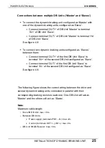
Connections between multiple DB Units (‘Master’ and ‘Slaves’)
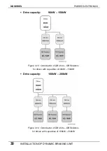
To connect the dynamic braking unit configured as ‘Master’ with
one of the dynamic braking units configured as ‘Slave’:
o
Connect terminal ‘OUT+’ of DB Unit ‘Master’ to terminal
‘IN+’ of DB Unit ‘Slave’.
o
Connect terminal ‘OUT-‘ of DB Unit ‘Master’ to terminal ‘IN-‘
of DB Unit ‘Slave’.
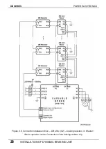
See figure 4.8.
To connect two dynamic braking units configured as ‘Slaves’
between them:
o
Connect terminal ‘OUT+’ of the first DB Unit ‘Slave’ to
terminal ‘IN+’ of the second DB Unit configured as ‘Slave’.
o
Connect terminal ‘OUT-‘ of the first DB Unit ‘Slave’ to
terminal ‘IN-‘ of the second DB Unit configured as ‘Slave’.
See figure 4.8.
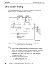
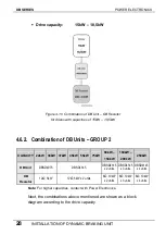
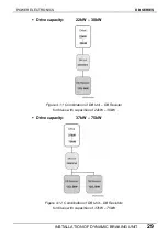
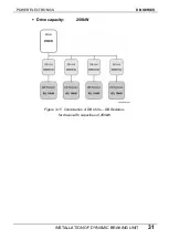
The following figure shows the correct wiring between the drive and
several dynamic braking units connected in parallel with their
corresponding braking resistors each one. One DB Unit will act as
‘Master’ and the others will act as ‘Slaves’.
Note:
Maximum cable length:
o
Drive
Î
DB Unit: max. 10m.
o
Between DB Units
•
Power supply (terminals P/B1 – N): max. 2m.
•
Control (terminals OUT+/- y IN+/-): max. 2m.
o
DB
Unit
Î
DB Resistor: max. 10m.
Summary of Contents for SDRIVE DB Series
Page 1: ...DB Series SDRIVE S D Y N A M I C B R A K I N G dynamic braking unit Getting Started Manual...
Page 2: ...dynamic braking unit Getting Started Manual Edition October 2007 VFDF01AI Rev A...
Page 3: ...DB SERIES POWER ELECTRONICS 2...
Page 5: ...DB SERIES POWER ELECTRONICS 4...
Page 7: ...DB SERIES POWER ELECTRONICS 6 INDEX...
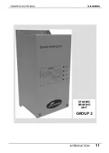
Page 12: ...POWER ELECTRONICS DB SERIES INTRODUCTION 11 DYNAMIC BRAKING UNIT GROUP 2...
Page 35: ...DB SERIES POWER ELECTRONICS 34 DYNAMIC BRAKING RESISTOR...
Page 36: ...POWER ELECTRONICS DB SERIES DYNAMIC BRAKING RESISTOR 35...
Page 38: ...www power electronics com...

