19
912.822.1 - GB
InstructIons pertaInInG to the InstaLLer
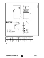
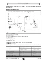
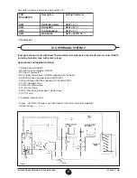
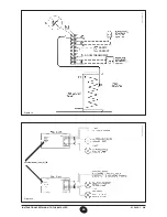
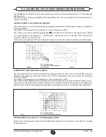
Figure 8
CT_0665 / 0906_2204
Applications (pumps, sensor, remote control ...) have to be connected to terminal as follows (see also section 12):
APPLICATION
TERMINAL BOARD
PRIMARY PUMP PLP
M1: A – B
HEATING PUMP P1
RVA 47
ROOM THERMOSTAT
RVA 47
FLOW/ RETURN SENSOR QAD 21
RVA 47
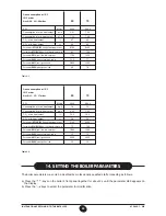
Parameter changes requires (see also section 14):
PCB PARAMETER
Description
Setting Parameter
H552
Hydraulic system
H552 = 80
H553
KonfigHKS
H553 = 21
H615
KonfigAusgang
H615 = 9
H632
WANFO Q8
00001111
If DHW circuit is required then DHW pump and DHW sensor have to be connected to terminal of RVA 47
Cascade Controller.
For more details refer to the instruction provided with the accessories RVA 47 and RVA 46 (compensated
circuit).

