29
912.822.1 - GB
InstructIons pertaInInG to the InstaLLer
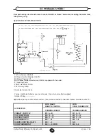
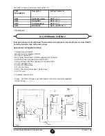
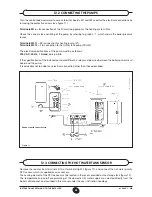
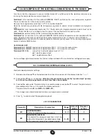
The SIEMENS model QAC34 outdoor temperature sensor must be connected to terminals 7-8 of terminal board
M2 in figure 12.
The procedures for setting the gradient of the temperature curve “kt” vary depending on the accessories con-
nected to the boiler.
a) Without QAA73 room temperature regulator:
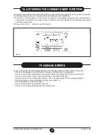
The temperature curve “kt” must be selected by setting parameter H532 as described in section 14 “setting the
boiler parameters”.
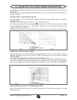
See graph 2 for selecting the curve referred to a room temperature of 20°C.
The chosen curve can be shifted by pressing the
(2), button (2) on the boiler control panel, and modifying
the value displayed by pressing the
and
. keys. See graph 3 for curve selection. (The example show
in graph 3 refers to the curve Kt=15).
Increase the value displayed if the room temperature required is not reached inside the premises for central heating.
b) With QAA73 room temperature regulator:
The temperature curve “kt” must be selected by setting parameter 70 “HC1 curve” of the QAA73 room tem-
perature control device as described in section 12.4 “QAA73: parameters which can be set by the installation
(service) engineer”.
See graph 4 for selecting the curve referred to a room temperature of 20°C.
The curve is shifted automatically on the basis of the room temperature set using the QAA73 climate control.
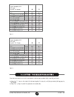
If the system is divided into zones, the temperature curve “kt” relating to the part of the system not controlled by the
QAA73 must be selected by setting parameter H532 as described in section 14 “setting the boiler parameters”.
Graph 2
Graph 3
TM = Flow temperature
Te = Composite outside temperature
Sth = Kt Curve
TM = Flow temperature
Te = Composite outside temperature
020523_0600
020523_1000
12.6 connecting the outdoor teMperature sensor probe
Graph 4
c) With AGU2.500 for control of a low temperature system:
Refer to the instructions provided with the AGU2.500 accessories for connection and control of a variable
temperature zone.

