10.0 Changing Components
20
10.2
Boiler Safety Thermostat
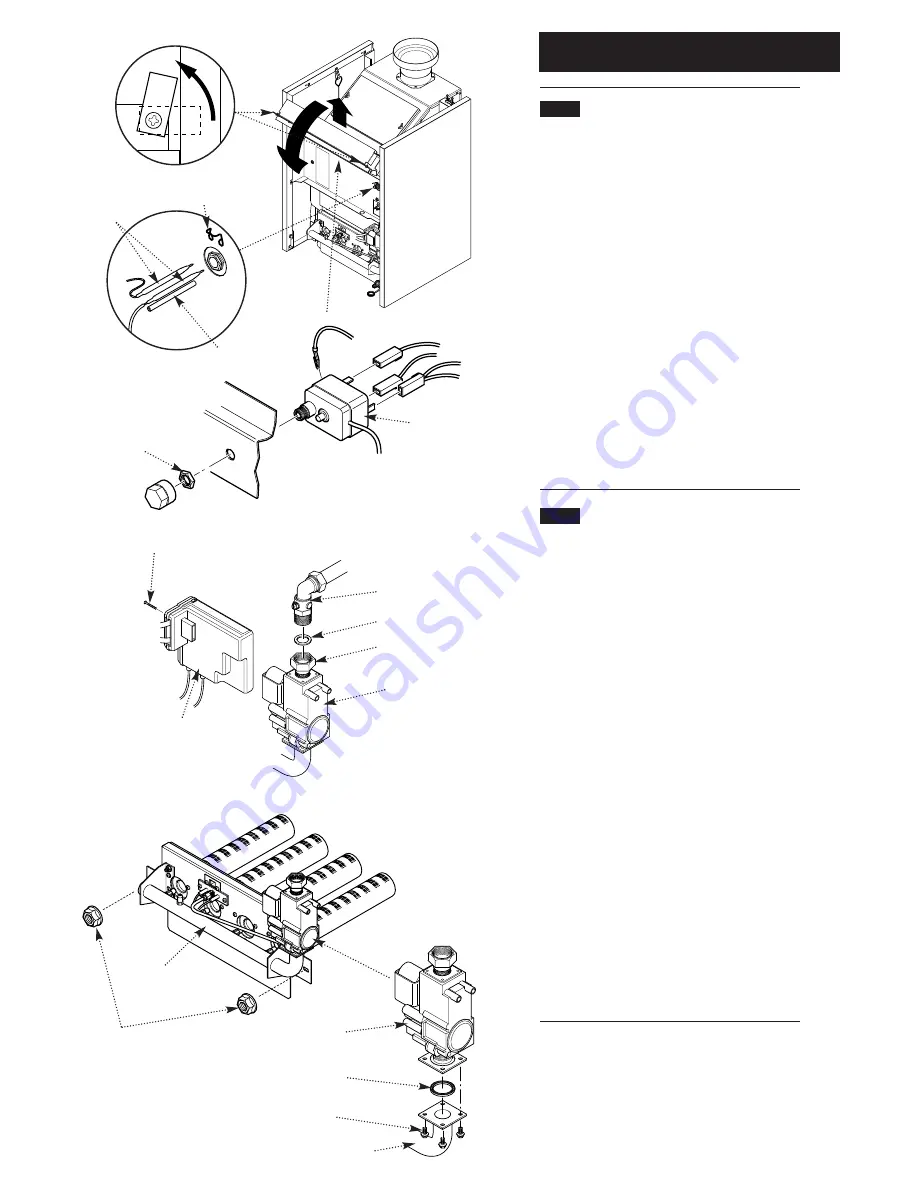
1. Swivel the two retaining plates through 90°.
Lift the control box slightly and allow it to hinge
forwards. Undo the two retaining screws and
remove the cover panel (Figs. 35 & 37).
2. After noting their position pull the wires from
the thermostat body (Fig. 38).
3. Remove the locknut securing the thermostat
to the control panel (Fig. 38).
4. Pull the spring clip off the thermostat pocket.
Withdraw both the boiler and overheat
thermostat phials and the spacer tube from the
pocket (Fig. 36).
5. Reassemble in reverse order, ensuring both
phials and the spacer tube are pushed fully into
the thermostat pocket and the capillaries are
retained by the clip.
10.3
Gas Valve
1. Undo the disconnecting union on the gas inlet.
Remove the screw securing the burner ignition
control to the gas valve. Draw the control off the
valve (Fig. 39).
2. Undo the two nuts securing the valve, injector
manifold and burner assembly to the boiler (Fig.
40).
3. Hold the manifold and carefully draw the
assembly away from the boiler. Retain the
washer from the gas inlet connection.
4. Undo the pilot feed pipe from the gas valve,
and slacken it at the pilot burner to allow it to
swing clear.
5. Undo the four screws securing the gas valve
to the injector manifold. Remove the valve and
seal (Fig. 41).
6. Check the condition of the seal previously
removed before fitting the new valve to the
injector manifold. Replace as necessary.
7. Reassemble in reverse order and check the
condition of the seal to be used on the
disconnecting union. Replace as necessary.
Securing Nuts
Manifold
Fig. 37
Fig. 40
Fig. 41
Gas Valve
Quad Seal
Burner Manifold
Valve Securing
Screws
Burner Ignition
Control
Securing Screw
Gas Valve
Disconnecting Union
Sealing Washer
Gas Cock
Fig. 39
Spring Clip
Thermostat
Phials
Spacer Tube
Fig. 36
Fig. 35
Lock Nut
Safety Thermostat
Fig. 38


