5. Commissioning – Page 18
5.1 Commission the Boiler
9)
With the main burner running, check for gas
soundness around the boiler using leak detection fluid.
Important
The commissioning and boiler adjustment must only
be carried out by a suitably qualified personnel.
Potterton Myson offer this service on a chargeable basis.
10)
Allow the system to reach maximum working
temperature and examine for leaks. Set the boiler
switch to 'Off' and drain the system whilst still hot.
Important
When checking for gas soundness open
all windows and doors in the room.
Extinguish all naked lights, cigarettes, pipes, etc.
Note:
Should the boiler fail to operate correctly refer to the
Fault Finding Guide on Page 24, and the
boiler wiring diagram on Page 25 for further information.
Open Vented Systems
- Remove the pump and flush the
system thoroughly with cold water. Re-fit the pump. Fill and
vent the system then check for leaks.
Sealed Systems - Note:
The system can be filled using a
sealed system filler pump with a break tank or by any other
method approved by the Local Water Authority. Refer to
Section 3.1, 'The System' on Page 6 of these instructions.
Remove the pump and flush the system thoroughly with cold
water. Re-fit the pump. Fill and vent the system until the
pressure gauge registers 1.5 bar (21.5 lbf/in²) and check for
leaks. Raise the pressure until the safety valve lifts, this
should occur within ± 0.3 bar of the preset lift pressure of 3
bar. Release water to attain the correct cold fill pressure.
All Systems
1)
The whole of the gas installation must be checked for
soundness and purged in accordance with BS 6891.
2)
Set the timer switch on the electronic control box to
position '0'
3)
Set the boiler switch on the user controls to 'Off'
4)
Turn the boiler gas service cock to the 'On' position and
then turn On the main gas supply.
5)
Ensure the system is full of water and that the pump
and radiator isolating valves are open.
6)
Switch On the main electricity supply at the isolating
switch or plug and socket.
7)
Ensure that the time control, if fitted, is in an ON
condition and that the room and cylinder. thermostat,
where fitted are set to high temperatures
11)
Re-fill and vent the system making a final check for
leaks.
On sealed systems adjust to the correct cold fill pressure.
Set the pressure gauge pointer to the system design
pressure.
If a by-pass circuit is fitted the by-pass valve should be
adjusted with the boiler operating under minimum load
conditions to maintain sufficient water flow through the boiler
to ensure that the overheat thermostat does not operate
under normal conditions.
Preliminary electrical system checks must be carried out.
They are:- Earth Continuity, Short Circuit, Polarity &
Resistance to Earth.
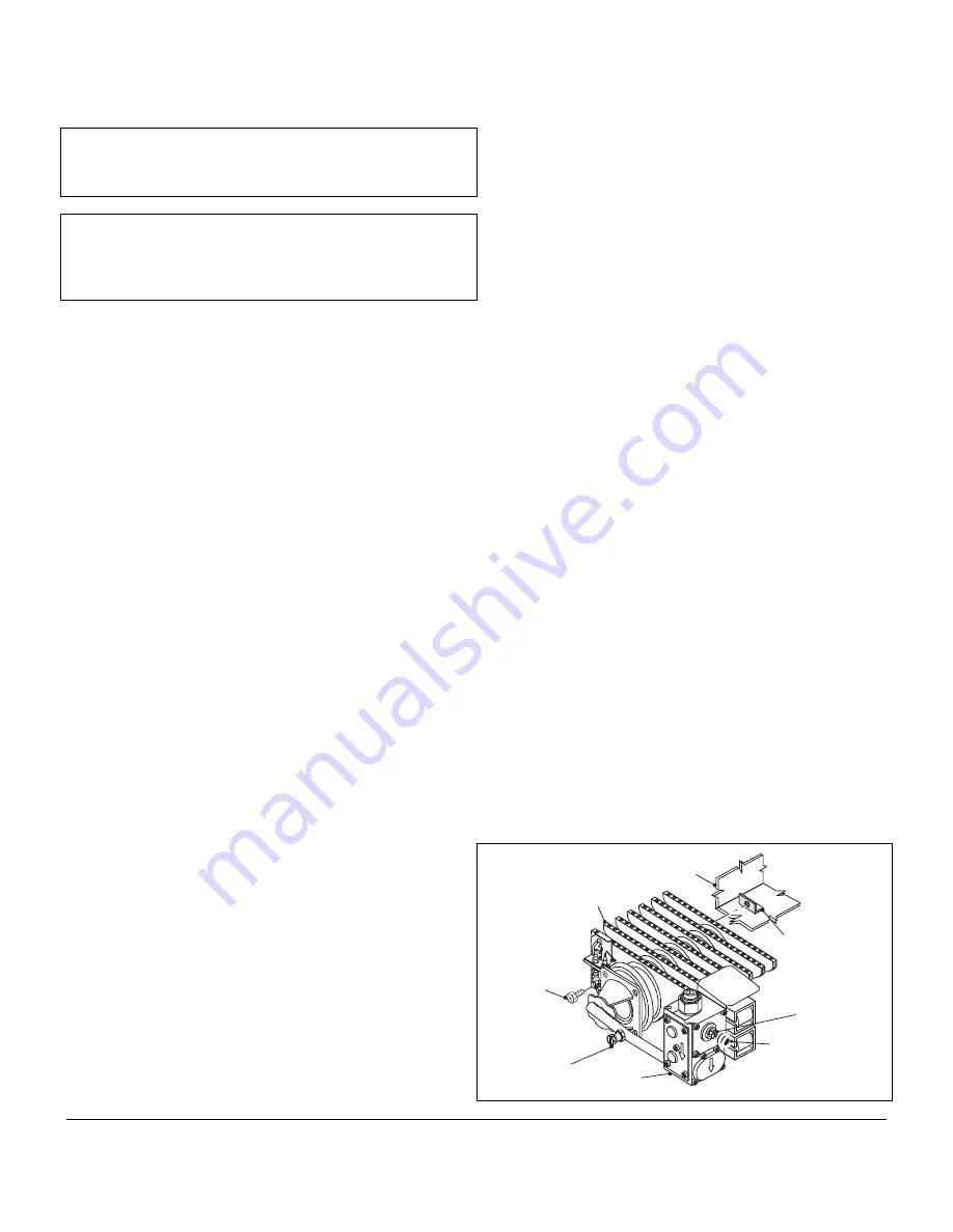
5.2 Final Adjustments
1)
Remove the screw and fit a pressure gauge to the
burner pressure test point on the burner feed pipe.
2)
Turn the boiler on and allow to run for 10 minutes.
3)
Check that the burner pressure is in accordance with
the information on the boiler data badge.
4)
If burner pressure adjustment is required, remove the
cap on the side of the gas valve and turn the screw
underneath - clockwise to increase pressure.
5)
Check at the Gas Meter that the heat input is correct.
6)
Shut down the boiler, remove the pressure gauge, re-
fit the screw and check for gas soundness. Re-fit the
cap (snaps on) onto the side of the gas valve.
7)
Set the timer switch to suit system reqirements. See
5.3, Timer Switch.
8)
Set the slider control on the user controls to 'Hi' and the
boiler switch to 'On'.
First time lighting:
The pilot will attempt to light, if the pilot
does not light within 60 seconds (due to air in the system)
the boiler controls will go to 'Lockout' and the LED on the
user controls will go Red. To re-start the lighting sequence
press the reset button on the user controls. There will be a
short delay before the lighting sequence starts.
When the pilot flame has established and the burner lights
the LED on the user controls will go Green.
Combustion
Chamber
Burner
Securing
Bracket
Main Burner
(45 Model)
Burner
Securing
Screw
Gas
Valve
Pressure
Test
Screw
B
B
4
5
0
1
9
B
Gas Pressure
Adjusting
Screw
Remove
Cap
Fig. 18
Summary of Contents for Housewarmer 45
Page 17: ...4 Installation Page 17 ...
Page 25: ...8 Electrical Diagrams Page 25 ...
Page 34: ...Installation Page 7 ...
Page 35: ...Installation Page 8 ...


