background image

3. Installation Requirements – Page 7

To size the expansion vessel it is first necessary to calculate
the volume of water in the system in litres. The following
volumes may be used as a conservative guide to calculating
the system volume.

Boiler Heat Exchanger:

4 litres

Small Bore Pipework:

1 litre per kW of system
output

Micro Bore Pipework:

7 litres

Steel Panel Radiators:

8 litres per kW of system
output

Low Water Capacity Radiators:

2 litres per kW of system
output

Hot Water Cylinder:

2 litres

If the system is extended, the expansion vessel volume may
have to be increased unless provision has been made for
extension. Where a vessel of the calculated size is not
available, the next available larger size should be used.
The boiler flow temperature is controlled at approximately
82°C.

The vessel size can now be determined from the information
in Table 1 where V = System volume in litres.

Cylinder

The hot water cylinder must be an indirect coil type or a
direct cylinder fitted with an immersion calorifier suitable for
operating at a gauge pressure of 0.3 bar (5 lbf/in

2

) in excess

of safety valve setting. Single feed indirect cylinders are not
suitable for sealed systems.

Method of Make-up

Provision shall be made for replacing water loss from the
system either:
i)

from a make-up vessel or tank mounted in a position
higher than the top point of the system, and connected
through a non-return valve to the system on the return
side of the hot water cylinder or the return side of all
heat emitters. or

ii)

where access to a make-up vessel would be difficult by
using the mains top up method or a remote automatic
pressurisation and make-up unit as shown in
Figs. 7 & 8.

Mains Connection

There shall be no connection to the mains water supply or to
the water storage tank which supplies domestic hot water
even though a non-return valve, without the approval of the
Local Water Authority.

Vessel Charge Pressure (bar)

0.5

1.5

Filling Point

Initial System Pressure (bar)

1.0

1.0

The system shall be fitted with a filling point at low level

Expansion Vessel Volume (litres)

V x 0.11

V x 0.087

which incorporates a stop valve to BS 1010 and a double

Table 1.

check valve (approved by the National Water Council) to be
fitted in this order from the system mains, see Fig. 7.

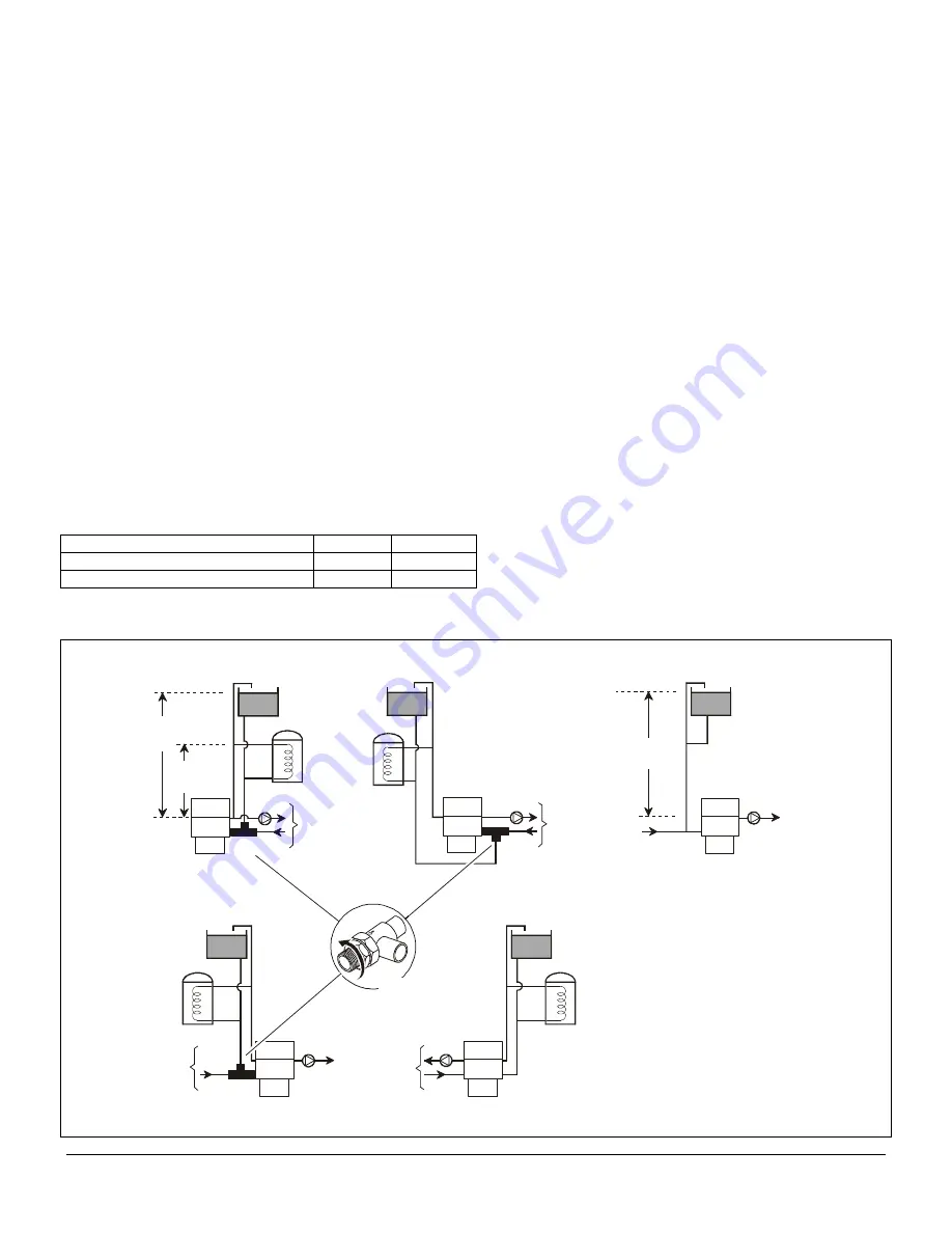
Flow

Flow

Return

Return

Central
Heating

Central
Heating

In

je

c

to

r

T

e

e

In

je

c

to

r

T

e

e

1.2

Metres

Min.

30.5

Metres

Max.

Water Level

Heat

Exchanger

Heat

Exchanger

Flow

Return

Central
Heating

Flow

Return

Central
Heating

Heat

Exchanger

30.5M Max.

0.9M Min.

Water Level

Flow

Fully

Pumped

System

Return

Heat

Exchanger

Heat

Exchanger

BBU Open Vented

System Variants

All Systems Illustrated
Can Be Fitted To The
Other Side Of the Boiler

On Combined Gravity
D.H.W. Pumped Heating
Systems The Injector
Tee Is To Be Fitted
Directly To The Boiler.
The Tee On The
Combined Flows Is
To Be Fitted As Close
To The Boiler As Possible

B

B

4

5

0

0

4

C

Injector Tee 
can be installed 
in any direction
see Fig 14

Fig 3

Summary of Contents for Housewarmer 45

Page 1: ...ns in accordance with the above regulations Failure to install appliances correctly could lead to prosecution Installation must be in accordance with these installation Service Instructions and the rules in force The polythene bags used for packaging are a potential hazard to babies and young children and MUST BE DISPOSED OF IMMEDIATELY LEAVE THESE INSTRUCTIONS WITH THE USER FOR USE ON FUTURE CALL...

Page 2: ...Assembly 21 6 6 Burner 21 6 7 Gas Valve 22 6 8 Overheat Thermostat 22 6 9 Control Thermostat 22 6 10 Electronic Control Box 22 6 11 User Control Box 22 6 12 Heat Exchanger 22 7 Fault Finding 24 8 Electrical Diagrams 25 9 Flow Diagrams 26 10 Short List Of Spares 27 Gas Fires The Potterton Housewarmer 45 55 Back Boiler Units can be fitted with a variety of approved Potterton Housewarmer Gas Fires Th...

Page 3: ...on Intermittent Pilot Intermittent Pilot Electrical Supply 230 240v 50HZ 230 240v 50HZ Fuse Rating External 3A 3A Packed Weight 41kg 90 5lbs 41kg 90 5lbs Water Capacity 4 litres 0 9 gal 4 litres 0 9 gal Gas Supply Connection 15mm Compression 15mm Compression Flow Connection Rc1 Rc1 Return Connection Rc1 Rc1 Injector Tee 28 22mm 28 22mm Maximum Flow Temperature 82 C 82 C Design Temperature Rise 11 ...

Page 4: ...uirements of the G A D and is permitted to carry the CE Mark The installation must be in accordance with the following Local Building Regulations Latest edition of I E E Regulations By Laws of the Local Water Undertaking and the Current Edition of the following standards BS 5440 1 Flues for gas appliances of rated input not exceeding 60kW BS 5440 2 Air Supply for gas appliances of rated input not ...

Page 5: ...ntrol device e g flue dampers economisers etc be directly connected to the appliance unless covered by these Installation Service Instructions or otherwise recommended in writing Any direct connection of a control device not approved by Potterton Myson Ltd could invalidate the CE Certification and normal appliance warranty ...

Page 6: ...r valve is used as shown in Figs 5 6 a by pass is not necessary since one circuit is always open Where a pair of two port valves are used a by pass is necessary It should be fitted with a lockshield valve and be adjusted to maintain a minimum flow through the boiler of 4 5 litres min 1 gal min see Figs 5 6 Systems fitted with controls which allow the boiler to operate when both the hot water and c...

Page 7: ...through a non return valve to the system on the return side of the hot water cylinder or the return side of all heat emitters or ii where access to a make up vessel would be difficult by using the mains top up method or a remote automatic pressurisation and make up unit as shown in Figs 7 8 Mains Connection There shall be no connection to the mains water supply or to the water storage tank which s...

Page 8: ...Mechanical Device E G Motorised Valve Gate Valve Should Be Fitted To The Radiator Circuit Where It Is Required To Prevent Gravity Circulation When The Pump Is Not Operating Fig 4 Flow Return Max 30 5m 100ft Min 0 9m 3ft Top Of Heat Exchanger Alternative By pass arrangement Using The Bathroom Radiator Fitted With Two Lockshield Valves Open V ented F ully P umped S ystem F itted With A Combined F ee...

Page 9: ... Valve Mains Water Supply Service Pipe Temporary Hose F illing A Sealed W ater S ystem Method 1 Note This Method Of Filling A Sealed System May Only Be Used If Acceptable To local Water Undertaking Mains T opping U p Method Heating System Hose Union BB45008A Fig 7 Overflow Mains Water Supply Cistern Stop Valve F illing A Sealed W ater S ystem Method 2 Note Cistern To Be Supplied Through A Tempory ...

Page 10: ...requirements are shown in the Installation Service Instructions supplied with the fire Note If the fireplace opening is to be newly constructed it is advisable to use the maximum dimensions shown in the gas fire Installation service Instructions On certain installations it may be convenient to run the gas or electricity supply through from the inside of the fireplace Using the dimensions given in ...

Page 11: ...isting chimney is used ensure that it is thoroughly swept before lining or connecting the boiler The liner must have an internal diameter of 125mm and be acceptable by British Gas 6 Care should be taken to avoid condensation in the flue 7 Where a flue liner is necessary use a non porous acid resistant type slide the liner into the chimney to finish at a height of 547mm above the hearth level on wh...

Page 12: ...mbustion and draught diverter dilution A permanent air vent must be fitted either directly to the outside of the building or into a room or space containing a permanent air vent of the same effective area The air vent must not enter the room through the builders opening The minimum effective area of the air vent required is as follows 45 Back Boiler and Gas Fire 73cm 55 Back Boiler and Gas Fire 89...

Page 13: ... pipe in the opening should be protected by wrapping in PVC tape Note The flue hood can be removed 4 nuts to improve access when connecting the system pipework Ensure the rope seal is correctly aligned on re assembly Remember The burner gas valve assembly will be fitted later ensure the system pipework will not pass through this area 9 Connect the system pipework to the boiler A drain off tap shou...

Page 14: ...h the hexagonal opening in the gas fire mounting bracket and Main Burner 55 Model Burner Securing Screw Gas Valve Combustion Chamber Gas Fire Supply Pipe Open Closed Boiler Gas Service Cock BB45033B Fig 15A secure using the locknut Connect the gas fire supply pipe to the isolation tap The gas fire isolation tap complete with locknut is supplied with the boiler Important Ensure the isolation points...

Page 15: ...Page 15 Insert Screws Into User Control User Control For Illusion Illusion 2 Straton Presence Presence 2 Firestar Knightsbridge See The Installation Service Instructions Supplied With The Fire Illusion Bracket Fig 16 ...

Page 16: ...on the electronic control box 5 Route a 4 core cable under the cable clamp and connect to the 6 way terminal block as follows Systems Using Pump Overrun Facility Re position link LK1 on the electronic control box so the link wires are to the top of the board Gravity Link Broken Permanent live to terminal marked MAINS L Neutral to terminal marked MAINS N Earth to terminal marked Switched live from ...

Page 17: ...4 Installation Page 17 ...

Page 18: ...ating switch or plug and socket 7 Ensure that the time control if fitted is in an ON condition and that the room and cylinder thermostat where fitted are set to high temperatures 11 Re fill and vent the system making a final check for leaks On sealed systems adjust to the correct cold fill pressure Set the pressure gauge pointer to the system design pressure If a by pass circuit is fitted the by p...

Page 19: ...ms position 1 should be used Other Boiler Controls No further setting or checking is necessary as all boiler mounted controls are designed so that if a fault should occur they will fail safe External Controls Check that any other external controls connected in the system such as clocks or thermostats control the boiler as required 5 4 Re check Flue Efficiency Before installing the fire front perfo...

Page 20: ...lve Nut Close Off Gas Remove Electrical Connector From Electronic Control Box Remove Gas Pipe Boiler Gas Service Cock BB45022C Fig 21 now be brushed clean and any deposits falling through can be swept out from the base of the boiler 6 1 Preparation 1 Isolate the electrical supply to the boiler 2 Isolate and remove the gas fire as shown in the gas fire Installation Service Instructions 6 2 Burner G...

Page 21: ... whilst gently bending the end of the tip with another pair Take care not to crack the ceramic liner 6 Re assemble in reverse order 6 6 Burner Servicing the Burner OxyPilot Main Burner Electrode Electrode Lead Earth Post Remove The Pilot Pipe OxyPilot Fixing Screws 2 Off BB45024B Fig 24 1 Perform section 6 2 2 Unscrew the M5 nut securing the burner cap and remove the cap Withdraw the internal baff...

Page 22: ...art and must be replaced complete 1 Disconnect the electrical connector at the control box 4 Re assemble in reverse order 6 9 Control Thermostat See Fig 27 1 Loosen the plastic screw and withdraw the control sensor 2 Disconnect the electrical connector at the control box 3 Re assemble in reverse order 6 10 Electronic Control Box See Fig 27 1 Disconnect all electrical connectors from the control bo...

Page 23: ...ing the flue liner and move it away from the top of the flue hood 5 Remove the 2 screws securing the boiler to the base of the opening 6 Carefully pull the complete boiler out of the fireplace 7 Remove the top 4 nuts and lift the flue hood off 8 Remove the bottom 4 nuts and lift the heat exchanger off the combustion chamber 9 Check the condition of the rope seals and fit new ones if required 10 On...

Page 24: ...N BLOCK FAULT EXTERNAL TO APPLIANCE CHECK ELECTRODE GAP REPLACE OR RECONNECT ELECTRODE LEAD AS NECESSARY CHECK OVERHEAT STAT LEADS AND CONNECTIONS REPLACE STAT IF NECESSARY IS RESISTANCE OF TEMPERATURE SENSOR BETWEEN 7K AND15K OHMS AT ROOM TEMPERATURE WITH TEMPERATURE CONTROL ON MAXIMUM IS THER MORE THAN 3v dc AND LESS THAN 6v dc BETWEEN CONECTOR TERMINALS PL6 8 AND PL6 9 ON THE FSC BOARD REPLACE ...

Page 25: ...8 Electrical Diagrams Page 25 ...

Page 26: ...ELAY RLP RELAY RLP RELAY RLL RELAY RLT PL6 9 PL6 8 PL6 3 PL6 2 PL6 5 PL6 7 BK RD WH GY OR PK Flame LED Lockout LED PL6 4 PL6 1 BL BL Reset Switch Located On User Control Unit PL2 4 RLT RLT T1 T5 PL4 3 PL4 4 RLF Main Gas Valve Pilot Gas Valve Spark Generator Ignition Electrode PL6 12 RLP Gravity Link Mains Transformer Tx1 20v 20v BL RLP RD BN YL Neutral BL BLUE BK BLACK BN BROWN PK PINK RD RED WH W...

Page 27: ...989 379 564 4 Electrode Lead Assembly 1 407738 114 608 5 Burner Assembly 45 Model 1 414718 289 810 Burner Assembly 55 Model 1 414719 289 811 6 Burner Injector 45 Model 1 625965 289 384 Burner Injector 55 Model 1 631334 7 PCB Flame Monitor Ignition Control 1 407725 289 835 Incl Item 8 8 Fuse F1 1A Anti surge T1AH 1 907609 289 841 Fuse F2 1A Anti surge T1AH 1 907609 289 841 9 Overheat Thermostat 1 4...

Page 28: ... SAFETY INSTALLATION AND USE REGULATIONS 1994 In your own interest and that of safety it is law that all gas appliances are installed by competent persons in accordance with the above regulations Failure to install appliances correctly could lead to prosecution The polythene bags used for packaging are a potential hazard to babies and young children and MUST BE DISPOSED OF IMMEDIATELY LEAVE THESE ...

Page 29: ...el 8 4 4 3 Burner Tray Gas Supply 9 5 Installing the Firebed Ceramics 9 6 Check Gas Pressure Operation of the Fire 10 7 Test for Spillage 10 8 Fitting the Facia 11 9 Complete the Installation 12 10 Servicing Cleaning 13 11 Replacement of Parts 14 11 1 General Access 14 11 2 Pilot Burner Assembly 15 11 3 Burner Injector 16 11 4 Lint Trap 16 11 5 Piezo Unit 16 11 6 Gas Tap 17 12 Short List of Spares...

Page 30: ...ia Boiler Isolation Valve at Right Hand side of fire Tap Combined Tap Flame Supervision Device and Piezo Burner Simplex Fixed Aeration Mica Filled Tray Injector Burner Marked Bray CAT 28 340 Injector Pilot Sit OxyPilot Pressure Test Point On Pipework at Left Hand Side of Fire Spark Gap 3 4mm Pre set Non Adjustable Gas Rate on Setting HI 0 49 m h 17 29 ft h Heat Input on Setting LO 3 8kW 12 965Btu ...

Page 31: ...d gas supply interruption is not the cause then the flue chimney MUST BE inspected and corrective action taken Call you local Gas Region or C O R G I Registered Installer IMPORTANT Certain types of wallcoverings e g Blown Vinyl are easily affected by heat They may shrink and discolour when close to a heating appliance Please bear this in mind when installing the fire Also because of the way hot ai...

Page 32: ... The surround s fireplace opening and flat area must comply with the dimensions shown in Fig 2 It must be sealed to the wall and infill panel if fitted correctly and have no combustible material protruding within the fireplace opening or exposed to the combustion products Shelves A combustible or non combustible shelf can be fitted above the fire provided it complies with the following guidelines ...

Page 33: ...ug the 4 marked mounting holes on the wall d Attach the foam strip along the sides and top of the surround at the rear e Using the 4 woodscrews supplied secure the surround to the wall Ensure the foam strip has been compressed f Remove from the bag of fittings and secure the tap mounting bracket to the outer metal surround using the 2 M4 x 8mm screws supplied g Insert the gas fire isolation tap th...

Page 34: ...Installation Page 7 ...

Page 35: ...Installation Page 8 ...

Page 36: ... 4 location screws b Insert the Burner Tray into the convector box so it locates onto the studs at the front c Using the wing nuts secure the Burner Tray to the convector box d Connect the inlet tube to the gas fire isolation tap If necessary the screws securing the isolation tap mounting bracket can be loosened to allow slight movement when aligning the tube to the tap Fully tighten the screws on...

Page 37: ...ame is not as described replace as shown in Section 11 2 e Push in and turn the control knob through to OFF f Disconnect the pressure gauge re fit the pressure test point screw and test for gas soundness 7 Test For Spillage Page 10 1 Fire Only a Close all doors and windows re light the fire pilot now only visible in a reflected form see Fig 12 Then turn to the HI setting b After 5 minutes light a ...

Page 38: ...suring that the 2 lugs at the top of the facia locate in the 2 holes at the top of the convector box c Loosen the 2 facia fixing bracket screws slide the fixing brackets back towards the facia and hook the Claws onto the ridges on the inside of the facia Tighten the screws sufficiently to bring the facia parallel to the fireplace wall Note Removal is the opposite of installation NSTALLER At this s...

Page 39: ...ng should be carried out at regular intervals as recommended by your local British Gas Region or C O R G I Registered Installer See Instructions For Use Page 8 e If service or spare parts are required always quote the Appliance Name Serial Number and G C Number shown on the Data Badge Show the user the position of the badge and advise them to write the Serial Number in the space provided on Page 9...

Page 40: ...dness after completing any servicing of gas carrying components and carry out functional checks of controls 10 1 Remove the Fire a Perform General Access See 11 1 Page 14 b Remove the screws securing the convector box to the outer metal surround and remove the convector box 10 2 Inspect Clean Components a Carefully brush off any dust or deposits from all the ceramic pieces Examine all the ceramics...

Page 41: ...cess a Carefully pull the plinth away from the fire b Remove the facia 2 by slackening off or removing the facia fixing brackets at the base of the facia Lift the facia off the convector box d Carefully remove all the ceramics and place to one side ...

Page 42: ...ve 2 screws securing the pilot sighting plate and remove the plate c Disconnect the union nut securing the pilot pipe to the pilot injector with 2 spanners d Disconnect the thermocouple from the back of the gas tap e Pull the electrode lead off the piezo unit f Remove 2 screws securing the A S D assembly and heat shield assembly to the burner box g Fit the new A S D assembly and check that the spa...

Page 43: ...11 4 Lint Trap a Perform General Access 11 1 b Remove the screw securing the lint trap to the injector box and carefully remove the lint trap 11 5 Piezo Unit a Remove the Plinth b Pull the control knob off the gas tap c Remove the 2 screws securing the bezel around the gas tap Remove the bezel d Pull the electrode lead off the piezo unit e Pull the circlip off the gas tap spindle and slide off the...

Page 44: ...he electrode lead off the piezo unit e Unscrew the thermocouple from the rear of the gas tap f Disconnect the 3 union nuts at the gas tap g Remove the 2 gas tap screws and withdraw the gas tap Notes on re assembly Ensure the electrode lead is positively located The thermocouple connection need only be finger tight and a quarter turn i Check for gas soundness and correct operation of the fire ...

Page 45: ...ludes Drg Ref 3 1 364 1044 3 385 855 Piezo Unit 1 942 9387 4 127 293 Pilot Burner Assembly Atmospheric Sensing Device 1 960 1433 5 127 022 Control Knob Assembly 1 503 1051 For Part Numbers of the ceramic bricks that make up the Coal Bed and the ceramic coals refer to the instruction sheet titled Fitting the Firebed Components Part Number 966 9350 3 Back Page ...

Reviews: