background image

24

SERVICING & REPLACING PARTS – Page 24

4)

INSULATION (Continued)

f)

Carefully replace burner.

g)

Refit hot surface igniter WARNING this component is
fragile and requires careful handling.

h)

Replacement is the reverse of removal.

5)

BURNER

7)

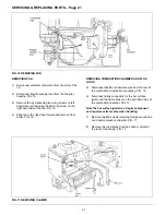
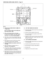
FLUE HOOD/COMBUSTION CHAMBER SEALS.

a)

Remove combustion chamber/fluehood as described
in “Servicing Boiler” See Fig.17.

b)

Remove old seal.

c)

Clean groove Lising a soft brush or dry lint free cloth.

d)

Ensure new seal is correct (flue hood and combustion
chamber require different seals).

e)

Lay seal over groove and gently push into the groove
until fully home.

See

 servicing instructions 

for reassembly of boiler.

8)

INJECTOR

a)

Remove decorative and functional doors as described
in 

“Servicing Boiler”.

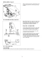
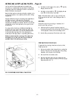
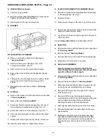
FIG. 20 REMOVAL OF BURNER

a)

Remove combustion chamber as described in

“Servicing Boiler”.

b)

Remove 8 M5 screws retaining burner to the
combustion chamber. FIG. 20.

c)

Remove burner from the combustion chamber.

d)

Ensure the burner is fitted with the gasket supplied
with it.

e)

Taking care not to damage the burner surface, install
new burner into combustion and secure with 8
screws.

f)

Reassemble as described in section 

“Servicing

Boiler”.

6)

SYPHON

a)

Remove decorative and functional doors as described
in 

‘Servicing Boiler”.

b)

Remove fan see 

“Servicing Boiler”

.

c)

Disconnect flexible condensate pipe from the rear of
the combustion chamber/sump casting. FIG. 16.

d)

Disconnect syphon from its wastepipe. See FIG. 11.

e)

Undo nut securing Syphon to the bottom of the boiler
casing.

f)

Relacement of the Syphon is the reverse of removal.

See servicing instructions for reassembly of boiler.

b)

Remove fan see 

“Servicing Boiler”

.

c)

Remove injector by unscrewing from gas supply pipe.

d)

Replacement is the reverse of removal.

9)

GAS VALVE ASSEMBLY

Warning always ensure before filling that the
correct assembly is being used, they are provided
preset for different boiler outputs.

a)

Remove decorative and functional doors as described
in 

“Servicing Boiler”.

b)

Remove fan as described in 

“Servicing Boiler”.

c)

Disconnect electrical supply lead at the gas valve by
removing the two retaining screws and unplug.

d)

Remove 4 M5 screws securing gas control valve to
boiler service cock.

e)

Remove 6 MS screws retaining gas assembly
mounting plate 4 MS on the left underside of the plate
and two within the casing. Remove MS screw
attaching the valve to its mounting bracket.

f)

Slide gas assembly forward and remove from boiler.

g)

Remove flexible tube from assembly and fit to new
gas assembly.

h)

Replacement is the reverse of removal ensuring a
new gasket is fitted between casing and mounting
plate and the “0” ring seal is correctly positioned
between the gas control valve and the boiler service
cock.

Summary of Contents for envoy 30

Page 1: ...ompetent persons in accordance with the above regulations Failure to install appliances correctly could lead to prosecution The polythene bags used for packaging are a potential hazard to babies and young children and MUST BE DISPOSED OF IMMEDIATELY LEAVE THESE INSTRUCTIONS WITH THE USER FOR USE ON FUTURE CALLS For Use With Natural Gas G20 Only At 2Ombar For Use in GB IE IMPORTANT PLEASE READ THIS...

Page 2: ... can be supplied with either of the following flue systems One metre 1 5 metre 2 metre 2 5 metre or 3 metre horizontal and one metre 1 5 metre 2 metre 2 5 metre or 3 metre vertical ACCESSORIES The following Potterton Myson controls are recommended for use with your boiler Electronic Programmer EP2002 EP3002 or EP6002 Cylinder Thermostat PTT2 or PTT1 00 Room Thermostat PRT2 or PRT100 Frost Thermost...

Page 3: ...2 5 2 9 3 2 3 7 4 2 Classification Burner Igniter Flame Detector Gas Control Valve Electrical Supply Fuse Rating External Packed Weight Water Capacity Gas Supply Connections Flow Connections Return Connections Condense Discharge Connection Maximum Flow Temperature Maximum Static Head Minimum Static Head Flue Size 12H C1 C3 1P20 Furigas Pre mix Norton 401S Hot Surface Morgan Matroc SIT Nova Mix 1 8...

Page 4: ...4 TECHNICAL DATA PAGE 4 FIG 2 GENERAL ARRANGEMENT ...

Page 5: ...Safety Regulations Manufacturers instructions must not be taken in any way as over riding statutory obligations ELECTRICITY SUPPLY A 230 volts 50Hz single phase electricity supply fused to 3 amperes must be provided in accordance with the latest edition of the lEE Wiring Regulations and any other local regulations that apply The current rating of the wiring to the boiler must exceed 3 amperes and ...

Page 6: ...mm 4 in at the bottom of the boiler VENTILATION If the boiler is to be installed in a confined space such as a cupboard the space will need ventilating Openings must be provided at the top and bottom of the cupboard each of which should have a free area as shown in TABLE 1 Further details for installation of a boiler within a compartment are given in BS 6798 If the openings draw air from outside t...

Page 7: ... the appliance MUST be turned OFF IMMEDIATELY FIG 3 FLUE TERMINAL POSITIONS Mm Distance mm A DIRECTLY BELOW AN OPENABLE WINDOW AIR VENT OR ANY OTHER VENTILATION OPENING 300 B BELOW GUTTER DRAIN SOIL PIPE 75 C BELOW EAVES HORIZONTAL FLUE ONLY 200 BELOW A BALCONY CARPORT ROOF NOT RECOMMENDED E FROM VERTICAL DRAIN PIPES AND SOIL PIPES 75 F FROM INTERNAL OR EXTERNAL CORNERS 300 G ABOVE ADJACENT GROUND...

Page 8: ... litres mm 1 gal mm see FIGS 4 5 Systems fitted with controls which allow the boiler to operate when both the hot water and central heating circuits are closed i e mechanically operated thermostatic control valves must be fitted with a by pass circuit capable of 1 Dissipating a minimum of 1kW 3400 Btu h 2 Maintaining a minimum water flow through the boiler of 9 litres mm 2 gal mm A suggested metho...

Page 9: ... the return side of hot water cylinder or the return Small Bore Pipework 1 litre per kW of system side of all heat emitters output or Micro Bore Pipework 7 litres Steel Panel Radiators 8 litres per kW of system output ii where access to make up vessel would be difficult by using the mains top up method or a Low Water Capacity 2 litres per kW of system remote automatic pressurisation and make up un...

Page 10: ...10 THE SYSTEM Page 10 FIG 4 OPEN VENTED FULLY PUMPED SYSTEM FITTED WITH A COMBINED FEED AND VENT FIG 5 FULLY PUMPED SEALED SYSTEM ...

Page 11: ...manufacturer s literature must be taken into account The pump may be fitted on either the flow or return and MUST be wired directly to the boiler terminal block It must be fitted with two isolating valves which are positioned as close to the pump as possible Closing of any valve must always leave the open vent unobstructed TABLE 2 Boiler Size Water Flow Rate Boiler Resistance Litres sec gal min mb...

Page 12: ...and making allowance for all horizontal flues to rise at an angle of 30 52mm per metre from the boiler place template in proposed boiler position Ensure the template is level and mark hole positions A If rear fluing mark flue outlet hole through template When side or vertically fluing extend flue outlet centre line on the template horizontally or vertically as appropriate and mark flue outlet hole...

Page 13: ...Using wall plugs and screws from accessory pack A attach boiler mounting plate to wall ensuring that it is level FIG 8 BOILER MOUNTING PLATE Lift the boiler onto the mounting plate and adjust vertical alignment using the adjustment screws at the rear of the boiler Refer to FIG 11 and secure the boiler to the mounting plate using the MS screw from accessory pack A FIG 9 LIFTING ADJUSTING AND SECURI...

Page 14: ...system pipework to the boiler A drain off tap should be installed close to the boiler Compression nuts and olives are provided in Accessory pack C Connect plastic condensate drain pipe to the outlet connection at the base of the boiler Connect the gas supply pipe to the inlet connection of the gas cock The gas cock should be temporarily disconnected from the gas control valve if a solder connectio...

Page 15: ...erside rear of the control box and connect to boiler terminal box as follows Permanent live to terminal marked L Neutral to terminal marked N Earth to terminal marked Switched live from external controls to terminal marked SwL Following the pump manufacturers instructions connect the pump live to terminal marked PUMP L The neutral and earth wires for the pump should be routed and connected to the ...

Page 16: ...s fuse failure incorrect polarity earth continuity and resistance to earth If a fault has occurred on the appliance the fault finding procedure should be followed See page 27 Fit the functional case door into position by lifting it onto the top hinge brackets and secure it with the lower two fixing screws FIRST LIGHTING WARNING Before lighting the boiler ensure that the functional case door HAS BE...

Page 17: ...ULD BE MADE TO ADJUST IT To check the correct operation of the gas valve follow the instructions below carefully a A good indication of correct operation of the boiler will be obtained by measuring the gas rate at the gas meter 1 Run the appliance for at least 10 minutes 2 With all other gas appliances turned off measure the gas rate at the meter for a period of at least 5 minutes Check that the m...

Page 18: ...to maintain sufficient water flow through the boiler to ensure that the overheat device does not operate under normal operating conditions BOILER CONTROL SWITCH In the mid i e position holds the boiler in a STANDBY condition In the position allows the boiler to operate automatically but controlled at a maximum flow temperature of 600 C In the position the boiler will operate automatically at a max...

Page 19: ... panels onto the boiler as illustrated ensuring that the four lugs on each panel are correctly located Slide in the bottom panel and push fully home Engage hooks on the top rear of the front panel into the slot in the top front corner of each side panel Lower the front panel to engage brass studs into the retaining clips press fully home to lock panel into position EXTERNAL CONTROLS Check that any...

Page 20: ...vicing of the boiler it is advisable to carry out a precheck on the boiler to establish that it is functioning correctly a Set boiler control switch to the mid i e and the display should read b Set boiler control switch to the display should read and the boiler should light Note If the boiler fails to start or does not follow the sequence above then refer to fault finding section on Page 27 WARNIN...

Page 21: ... from boiler FIG 16 REMOVING COMBUSTION CHAMBER AND FLUE HOOD 5 Disconnect flexible condensate pipe from the rear of the combustion chamber sump casting FIG 16 6 Disconnect inline connectors for the hot surface igniter and the flame sensor on the right hand side of the combustion chamber FIG 17 Note the hot surface igniter is a fragile component and requires extreme care when handling 7 Remove two...

Page 22: ...xchanger remove all deposits from between the fins 4 Examine top and bottom sealing face of the heat exchanger for deep scratches and remove any debris with a soft brush to provide a smooth flat sealing face 5 Examine Syphon for evidence of leakage or build up of debris Note Place a catch tray beneath the syphon cleaning eye plug and remove plug this should remove any debris which has collected in...

Page 23: ...on chamber See FIG 19 c Replacement of the sensor is the reverse of removal ensure new gasket is always fitted switching off the appliance at the external isolating switch b Isolated the gas supply at the boiler service cock If the combustion chamber has been removed follow procedure in Service section Re assembly of boiler 1 FAN a Follow procedure in Preparation for servicing at the beginning of ...

Page 24: ... Remove fan see Servicing Boiler c Disconnect flexible condensate pipe from the rear of the combustion chamber sump casting FIG 16 d Disconnect syphon from its wastepipe See FIG 11 e Undo nut securing Syphon to the bottom of the boiler casing f Relacement of the Syphon is the reverse of removal See servicing instructions for reassembly of boiler b Remove fan see Servicing Boiler c Remove injector ...

Page 25: ...ensor and remove it by gently squeezing two protruding plastic lugs and while still squeezing pull from its housing c Replacement is the reverse of removal ensure when fitting new sensor that sensor tip is coated with heat conducting paste and that it is correctly located and firmly home in its housing 12 DRY FIRE TEMPERATURE SENSOR a Remove decorative and functional doors as described in Servicin...

Page 26: ...corative functional doors as described in Servicing Boiler b Remove screw retaining access door on under side of boiler FIG 22 c Remove screw retaining control front panel and tray FIG 22 d Gently pull front panel forward removing connectors from the control as they become accessible FIG 23 e Remove old fuse and replace with the correct Potterton component T3 ISA Pt 933005 f Replacement is the rev...

Page 27: ...tly fitted Check sensor Case temperature Temperature within boiler casing too high See chart Dry fire Boiler has been fired without water Check system Flow sensor Sensor failed open or closed circuit Replace sensor Return sensor Sensor failed open or closed circuit Replace sensor Case sensor Sensor failed open or closed circuit Replace sensor Dry fire sensor Sensor failed open or closed circuit Re...

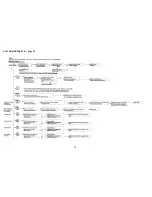
Page 28: ...28 FAULT FINDING CHART 1 Page 28 ...

Page 29: ...29 FAULT FINDING CHART 2 Page 29 ...

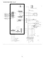
Page 30: ...30 BOILER INTERNAL WIRING Page 30 ...

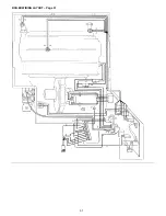
Page 31: ...31 BOILER WIRING LAYOUT Page 31 ...

Page 32: ...the burner pressure to maintain safe combustion Before attempting to adjust the gas valve a check must be conducted on the whole appliance to ensure that any other faults present are found and rectified SETTING THE BURNER PRESSURE WARNING Setting the burner pressure requires the following equipment ESSENTIAL 1 A differential pressure gauge or U tube manometer capable of measuring pressures in the ...

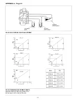
Page 33: ...33 APPENDIX A Page 33 FIG 24 GAS CONTROL VALVE ADJUSTMENT FIG 25 PRESSURE ADJUSTMENT GRAPH Signal and Burner Pressures are based on a Burner Injector with a nominal flow rate ...

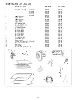
Page 34: ...ers 409584 114569 Fan 50 60 80 Boilers 409592 E00040 4 Control Assembly 407734 114629 5 Temperature Sensor 404513 378868 6 Burner 30 Boiler 414727 378870 Burner 40 Boiler 414728 378871 Burner 50 Boiler 414729 378872 Burner 60 Boiler 414730 378873 Burner 80 Boiler 414731 378874 7 Burner Gasket 236120 114561 8 Fan Outlet Gasket 236253 114596 9 Hot Surface Igniter 407728 378869 10 Flame Sensor 407729...

Page 35: ... Seals Material Ceramic Fibre Alumino Silicone Fibre Description Boards Ropes Gaskets Known Hazards Some people can suffer reddening and itching of the skin Fibre entry into the eye will cause foreign body irritation Irritation to respiratory tract Precautions People with a history of skin complaints may be particularly susceptible to irritation High dust levels are only likely to arise following ...

Page 36: ...36 Back Page ...
Reviews: