


6
INSTALLATION REQUIREMENTS – Page 6
Where a room-sealed appliance is installed in a room
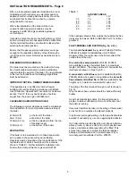
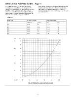
TABLE 1
containing a bath or shower, any electrical switch or
AIR VENT AREAS
appliance control, utilising mains electricity should be
in
2
cm
2
so situated that it cannot be touched by a person
30
16
103
using the bath or shower.
40
21
135
50
26
170
Where the installation of the boiler will be in an
60
32
206
unusual location, special procedures may be
80
43
277
necessary and BS.6798 gives detailed guidance
on this aspect.
It should be noted that due to the high efficiency of this
boiler a white plume of condensate will be emitted from
the flue terminal therefore care should be taken when
selecting the terminal position.
Ensure that the gas supply pipe and meter are large
enough for the appliance and any others that may be
run off the same meter. Reference should be made to
BS.6891.
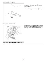
BOILER MOUNTING SURFACE
The boiler must be mounted on a flat wall, which may
be of combustible material and must be sufficiently
robust to take the weight of the boiler. The requirements
of the local authorities and the Building Regulations
must be adhered to.
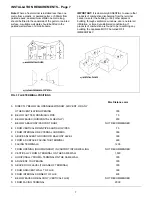
IMPORTANT NOTICE:–TIMBER FRAMED HOUSES
If the appliance is to be fitted in a timber framed
building, it should be fitted in accordance with British
Gas Publication ‘Operational Procedures for Customer
Service’ Part 19. If in any doubt, advice should be
sought from the local region of British Gas.
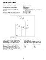
CLEARANCES AROUND THE BOILER
The following minimum clearances must be maintained
after installation, for correct operation and servicing of
the boiler:
610mm (2ft)
at the front of the boiler
5mm (0.2 in)
each side of the boiler
140mm (5.5 in)
at the top (measured from the top
of the boiler case)
100mm (4 in)
at the bottom of the boiler
VENTILATION
If the boiler is to be installed in a confined space such
as a cupboard, the space will need ventilating.
Openings must be provided at the top and bottom of the
cupboard each of which should have a free area as
shown in TABLE 1. Further details for installation of a
boiler within a compartment are given in BS.6798.
If the openings draw air from outside the building the free
areas may be halved. Refer to BS.5440 Part 2 for further
guidance.
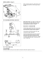
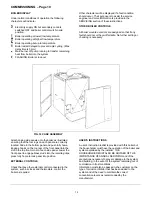
FLUE TERMINAL AND DUCTING (Fig. 3a, b & c)
The standard
horizontal
flue system (Potterton Part No.
236346) is suitable for installations up to 1030mm,
measured from the centre line of the boiler outlet to the
outside face of the wall.
One metre flue extension kits
(Part No. 430085)
are available to extend horizontal flues to a maximum
length of 2920mm. The siting positions for horizontal flue
terminals are shown in Figs. 3a, b & c.
A concentric vertical flue
system is available (Part No.
236348) which when used in conjunction with
one metre
flue extension kits (Part No.
430085) is suitable for flue
heights up to 3 metres to terminate through a roof.
The siting of the flue terminal through a roof is shown in
Fig. 3c.
Only the above flue systems should be used with Envoy
boilers.
As with all condensing boilers, the flue will produce a
plume of visible condensation for much of the time that
the boiler is running.
Care must therefore be taken in the siting of the terminal
so as not to be a nuisance to adjacent property.
In particular, prolonged wetting of a facing wall should be
avoided, if necessary by use of an appropriate deflector.
If a horizontal flue is sited less than 2m above a balcony,
above ground, or above a flat roof to which people have
access, a suitable terminal guard must be fitted. This
serves two purposes, to protect the terminal against
damage or interference and to protect passers-by. A
terminal guard is available (Part No. 236591).
Summary of Contents for envoy 30
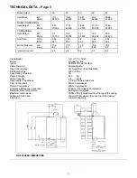
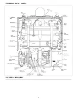
Page 4: ...4 TECHNICAL DATA PAGE 4 FIG 2 GENERAL ARRANGEMENT ...
Page 28: ...28 FAULT FINDING CHART 1 Page 28 ...
Page 29: ...29 FAULT FINDING CHART 2 Page 29 ...
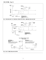
Page 30: ...30 BOILER INTERNAL WIRING Page 30 ...
Page 31: ...31 BOILER WIRING LAYOUT Page 31 ...
Page 36: ...36 Back Page ...