23
SERVICING & REPLACING PARTS – Page 23
7)
Replacement of components is the reverse of
removal.
Note
great care should be taken not to damage the flue
hood and combustion chamber seals during replacement
of these assemblies.
8)
When refitting straps ensure that they are located
correctly in the guides on both the flue hood and
combustion chamber.
9)
Ensure that screws are fully tightened and clamps fix
the combustion chamber and flue hood securely.
10)
Ensure connection from sump to syphon is made
before refitting fan.
11)
Ensure that the gaitor between the flue hood and
elbow is correctly positioned untwisted and forms a
good seal to both components.
12)
Relight the boiler as described by following the
lighting procedure in the commissioning section of
these instructions.
REPLACEMENT OF PARTS
Before replacing any component carry out pre-check
detailed at the beginning of the Service section and
then refer to fault finding section of these
instructions.
WARNING
Before the start of any servicing or replacement of parts
ensure that you have:
a)
Switched off at the external electrical supply by
removing the plug from the wall socket or by
3)
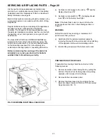
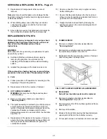
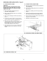
FLAME SENSOR
a)
Remove combustion chamber as described in
“Servicing Boiler”.
b)
Remove screw retaining sensor and withdraw from
the combustion chamber. See FIG. 19.
c)
Replacement of the sensor is the reverse of removal,
ensure new gasket is always fitted.
switching off the appliance at the external isolating
switch.
b)
Isolated the gas supply at the boiler service cock.
If the combustion chamber has been removed follow
procedure in Service section “Re-assembly of boiler”
1)
FAN
a)
Follow procedure in “Preparation for servicing” at the
beginning of the servicing section.
b)
Replacement of fan is the reverse of removal.
2)
HOT SURFACE IGNITER
WARNING
this component is fragile and requires
careful handling.
a)
Remove combustion chamber as described in
“Servicing Boiler”.
b)
The igniter assembly is retained by two MS pozi drive
screws. Remove screws and carefully remove old
igniter, if the igniter has become damaged, invert the
combustion chamber and shake gently to allow
damaged segments to be removed from the chamber.
See FIG. 19.
c)
Replacement of the igniter is the reverse of removal
ensure that a new sealing gasket is always fitted and
that a good seal is made between the igniter and
combustion chamber.
FIG. 19 HOT SURFACE IGNITER & FLAME SENSOR
4)
INSULATION
Note all four insulation pads must be replaced.
a)
Remove combustion chamber as described in
“Servicing Boiler”.
See FIG. 17.
b)
Remove burner FIG. 20 hot surface igniter and flame
sensor. FIG. 19.
c)
Remove old insulation.
d)
Replace front pad first ensuring that bevelled edge is
uppermost and fits into the chamber correctly.
e)
Fit rear pad and use end insulation to retain rear pad.
Summary of Contents for envoy 30
Page 4: ...4 TECHNICAL DATA PAGE 4 FIG 2 GENERAL ARRANGEMENT ...
Page 28: ...28 FAULT FINDING CHART 1 Page 28 ...
Page 29: ...29 FAULT FINDING CHART 2 Page 29 ...
Page 30: ...30 BOILER INTERNAL WIRING Page 30 ...
Page 31: ...31 BOILER WIRING LAYOUT Page 31 ...
Page 36: ...36 Back Page ...

