background image

QUESTIONS? 

Ask the experts at POSMicro.com.


1.800.241.6264

   Live Chat Now

   [email protected]

Monday - Friday 6 AM to 5 PM Pacific 

Time

BULk DISCOUNTS

FREE SHIPPING*

SE HaBLa 

ESpa

ñ

OL

*Free ground shipping to the continental USa on orders over $100.

For Help Call 

1.800.241.6264

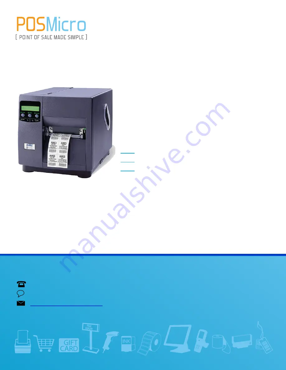
Datamax I Class
Manual

THIS DOWNLOAD APPLIES TO THE FOLLOWING

I4208

I4212

I4308

Summary of Contents for I4208

Page 1: ...port POSMicro com Monday Friday 6 AM to 5 PM Pacific Time Bulk Discounts FREE SHIPPING SE Habla Español Free ground shipping to the continental USA on orders over 100 For Help Call 1 800 241 6264 Datamax I Class Manual THIS DOWNLOAD APPLIES TO THE FOLLOWING I4208 I4212 I4308 ...

Page 2: ...Operator s Manual ...

Page 3: ......

Page 4: ...tates do not permit the exclusion of incidental or consequential damages and in those states the foregoing limitations may not apply The warranties here give you specific legal rights and you may have other legal rights which vary from state to state Firmware Software Agreement The enclosed Firmware Software resident in the Printer is owned by Licensor or its suppliers and is licensed for used onl...

Page 5: ...93 Class B EN 50024 1998 EN61000 4 2 1995 4kV CD EN61000 4 3 1996 3V 80 AM EN61000 4 4 1995 500V Signal Lines 1 kV AC Power Lines EN61000 4 5 1995 1 kV EN61000 4 6 1996 3V 80 AM EN61000 4 8 1994 1 A M EN61000 4 11 1994 EN61000 3 2 1995 EN61000 3 3 1995 Safety This product complies with the requirements of IEC 60950 Gost R GB4943 2001 GB9254 1998 and GB17635 1 2003 FCC This device complies with FCC...

Page 6: ...all warning instruction labels on the printer Install the printer on a flat firm surface Do not place the printer on or near a heat source To protect your printer from overheating make sure no openings on the printer are blocked Never insert anything into the ventilation slots and openings of the printer Do not use the printer near water or spill liquid into it Ensure that the AC power source matc...

Page 7: ......

Page 8: ...Additional Requirements 8 3 Setting up the Printer 9 3 1 Installation 9 3 1 1 Communications 10 3 2 Media Loading 11 3 2 1 Loading Roll Media 12 3 2 2 Loading Fan Fold Media 13 3 3 Media Sensor Adjustment 15 3 4 Ribbon Loading 16 3 5 Quick Calibration 17 4 Using the Control Panel 19 4 1 Operation 19 4 1 1 Display and Indicator Lights 19 4 1 2 Ready Mode Normal Operation 20 ...

Page 9: ...nications 44 4 2 7 Diagnostics 53 4 2 8 MCL Options 55 4 3 The Test Menu 56 4 3 1 Print Quality Label 56 4 3 2 Configuration Label 56 4 3 3 Ribbon Test Label 57 4 3 4 Validation Label 57 4 3 5 Print Last Label 57 4 3 6 User Defined Label 57 5 Operating Adjusting and Maintaining the Printer 59 5 1 Displayed Messages 59 5 1 1 Prompts and Condition Messages 59 5 2 Calibration 61 5 2 1 Standard Calibr...

Page 10: ...e 75 5 6 1 Cleaning the Printhead 76 5 6 2 Cleaning the Platen Roller 78 5 6 3 Cleaning Interior and Exterior Surfaces 79 5 7 Application Updates 79 5 7 1 Updating from Ready Mode 79 5 7 2 Updating from Download Mode 81 5 7 3 Possible Problems 82 5 8 Boot Loader Updates 83 6 Troubleshooting 85 6 1 Problem Resolution 85 6 1 1 General Resolutions 85 6 1 2 Warning and Fault Messages 89 6 2 Hex Dump M...

Page 11: ...ppendix A 105 Module Assignments 105 Print Resolutions and Maximum Label Widths 105 Available Speeds and Default Settings 106 Appendix B 107 Custom Adjustment Ranges 107 Column Row Emulation Ranges 107 Appendix C 109 Menu Multi Language Support 109 Appendix D 113 Configuration Files 113 Appendix E 115 Printer Driver and Port Setup 115 Glossary 119 ...

Page 12: ...ructions provided with your labeling software or if you wish to write custom programs a copy of the Class Series 2 Programmer s Manual can be found on the Accessories CD and at our web site at http www datamax oneil com As detailed below each model offers many standard and optional features to meet all your label generation needs 1 1 1 Standard Features The model number located on the back of the ...

Page 13: ...Optional Features available except as noted The following optional features are offered for the printer Cutter Light Duty A rotary mechanism that cuts material with a maximum thickness of 005 inches 127 mm in lengths as small as 1 25 inches 31 8 mm An adjustable collection tray 200 label capacity can also be added Cutter Standard Duty A rotary mechanism that cuts material with a maximum thickness ...

Page 14: ...s Real Time Clock keeps the time and date for labeling functions GPIO Port controls print functions via an external device e g a label applicator ILPC Fonts optional extends printing capabilities with CG Times Kanji Gothic B Simplified Chinese GB Korean Hangul scalable fonts MCL Serial Port optional allows use with MCL application programs and firmware Internal Rewinder An internal device capable ...

Page 15: ...pared to most direct thermal media Twinax Coax Interface A slide in circuit card that provides connectivity to AS 400 and System 3X Twinax host systems or 3270 type host systems cabling included USB Port A slide in circuit card that provides a Universal Serial Bus Version 1 1 interface for Windows printing environments Option Installation Experience levels for option installations are detailed bel...

Page 16: ...Installer Peel and Present Mechanism Operator Present Sensor Operator RFID Ready DMX Certified Technician RS 422 Serial Interface DMX Certified Technician Thermal Transfer Operator Twinax Coax Interface DMX Certified Technician USB Port DMX Certified Technician ...

Page 17: ...6 I Class ...

Page 18: ...tify the shipping company before acceptance Complete the steps below to ready the printer for use A With the arrow pointing upward open the box B Remove Accessories Box C Tilt the box sideways and then slide out the printer D Place the printer in an upright position and remove the packing foam bag and tape Note Save the carton and packaging materials for future use ...

Page 19: ...ord Accessories CD Any special or additionally purchased items 2 1 2 Additional Requirements Other items can also be needed for operation An interface cable see Section 3 1 1 Applicable media see Section 7 3 Applicable software consult the Accessories CD ROM and see Appendix E for details or refer to your dealer or Datamax O Neil for information ...

Page 20: ... an appropriate interface cable from the host to the printer see Section 3 1 1 C Turn ON the Host Computer D Ensure that the printer s Power On Off Switch is in the OFF position Connect the AC Power Cord to the AC Power Connector and then plug the AC Power Cord into a properly grounded AC Outlet Note When interfacing ensure AC power has been turned OFF and always apply power to the Host before the...

Page 21: ...l interface has two menu selectable modes of operation Unidirectional mode is forward channel communication and requires a Centronics cable with a 36 pin male connector Bidirectional mode is IEEE 1284 Compliant using forward and reverse channel communications and requires an IEEE 1284 cable with a Centronics 36 pin male connector Serial Port The serial interface supports RS 232C and if equipped op...

Page 22: ...ide outward and then rotate it downward D If using roll media on a 1 5 inch 38mm core grasp then pull firmly outward to remove the 3 Inch Media Hub otherwise go to Step E 1 5 Inch Media Hub 3 Inch Media Hub Media Guide Printhead Latch Printhead Assembly E Proceed according to the media type For Roll Media see Section 3 2 1 or For Fan Fold Media see Section 3 2 2 ...

Page 23: ...Media Guide Backstop Media Hub B Route the Media under the Media Idler through the Media Sensor and then straight out the front of printer Media Idler Media Guide Media Sensor Media C Raise then slide the Media Guide over so that it rests lightly against the edge of the media D Position the Media Sensor see Section 3 3 ...

Page 24: ...splayed press and hold the FEED Key until at least one label gap or mark is advanced see Section 3 5 Printhead Latch Printhead Assembly Note Adjust the Leveling Cam if using narrow media see Section 5 4 1 3 2 2 Loading Fan Fold Media A With the Fan Fold Media source aligned to the Bottom or the Rear Media Slot insert the media If using reflective media be sure that the black mark is facedown Fan F...

Page 25: ...edia Guide over so that it rests lightly against the edge of the media E Position the Media Sensor see Section 3 3 F If using thermal transfer media load ribbon see Section 3 3 otherwise go to Step G G Lower the Printhead Assembly and rotate the Printhead Latch into the locked position Close the cover then turn ON the printer After READY is displayed press and hold the FEED Key until at least one ...

Page 26: ...Tab to position the Sensor Eye Mark as described in the table below Afterward if necessary return to the previous section to complete the setup Media Type Sensor Eye Mark Position Die cut Near the middle of the label Notched Centered over the notch Reflective Centered over the black mark Continuous Near the middle of the media Media Sensor Printhead Assembly Sensor Eye Mark Slide Tab Notes 1 For S...

Page 27: ...ead Assembly then up and around the Ribbon Take Up Hub Wind the ribbon several times in a clockwise direction around the Ribbon Take Up Hub to secure it C If loading media return to the media loading instructions otherwise lower the Printhead Assembly and rotate the Printhead Latch into the locked position Ribbon Take Up Hub Printhead Latch Ribbon Idler Ribbon Roll Ribbon Supply Hub Directional Ar...

Page 28: ...or after changing your media type Ensure that media is loaded and that the Media Sensor is adjusted Then with the printer idle press and hold the FEED Key Allow at least one complete label to advance then release the key Upon successful completion CALIBRATION COMPLETED and then READY will be displayed Notes If UNCALIBRATED is displayed see Section 5 2 If the printer displays CANNOT CALIBRATE or st...

Page 29: ...18 I Class ...

Page 30: ...abel counts during batch jobs When in Menu Mode the System Menu and Displayed Messages The Ready Light provides operational state information ON indicates Ready Mode SLOW FLASHING indicates Menu Mode and FAST FLASHING indicates data reception The Stop Light indicates a paused condition The Error Light indicates the following conditions see Section 6 1 2 SLOW FLASHING indicates a Warning and FAST F...

Page 31: ...tes a soft reset see Section 5 3 1 The MENU Key toggles the Ready and Menu Modes and while in Ready Mode pressing and holding it adjusts the LCD Contrast The TEST Key enters and exits the Test Mode 4 1 3 Menu Mode Configuration Ready Light Flashing The DOWN ARROW Key scrolls to a previous menu item and also decrements numerical values for most menu selections The UP ARROW Key scrolls to the next m...

Page 32: ... test label quantity except the Configuration Label always one and holding down the key scrolls the quantities The ESCAPE Key exits the Test Mode The TEST Key prints the selected label at the selected quantity During printing this key also cancels the test Pressing and holding it for four seconds initiates printhead cleaning see Section 4 2 2 Note Test Mode functions are disabled while processing ...

Page 33: ...or unauthorized Menu System changes see Section 4 2 5 4 The commands from your host computer may in some cases override the menu settings see Section 4 2 6 for setting controls 5 Depending upon the installed firmware some of the menu selections represented below may not appear in your printer 6 Options or items not detected by the printer may indicate NOT INSTALLED when accessed in the menu 4 2 1 ...

Page 34: ...will save these changes or pressing ESC will discard them Note If required a reset will automatically occur The following designations are used throughout the menu listings below Symbol Definition Denotes a firmware default setting or value Denotes a setting can only be changed via the menu 4 2 2 Media Settings The Media Settings menu contains label and ribbon settings and printhead maintenance se...

Page 35: ...9 99 Is the length of travel to detect a TOF gap or mark Note This distance should be 2 5 to 3 times the length of the label PAPER OUT DISTANCE Sets the Out Of Stock fault empty distance where 00 25in 0 99 99 Is the attempted length of feed before empty is declared Note If using clear or translucent media this setting should be longer than the length of the label LABEL WIDTH Sets the maximum print...

Page 36: ...lows manual entry of paper gap or mark and empty threshold values SENSOR GAIN Adjusts the sensor sensitivity PRINTHEAD CLEANING Controls the automatic cleaning alert and function where CLEAN HEAD SCHEDULE 000 in 1000 Specifies the amount of media times one thousand that can be used before a print head cleaning warning will be issued If exceeded three times however a fault will be declared Note Zer...

Page 37: ... the rate of label movement between printing areas where XXin sec X XX Is the speed setting see Appendix A for the model dependant default and range REVERSE SPEED Controls the rate of label movement during backup positioning where XXin sec X XX Is the speed setting see Appendix A for the default and range SLEW SPEED Controls the rate of label movement between printing areas when using the GPIO opt...

Page 38: ...cal compensations sometimes evident when multiple printers share label formats or for special printer specific formatting adjustments where DARKNESS 32 1 64 Controls the printhead strobe time see HEAT above to fine tune the solid areas of the image CONTRAST 32 1 64 Fine tunes the gray areas of an image ROW ADJUST 000 DOTS XXX XXXX Shifts the vertical SOP position to fine tune the ROW OFFSET settin...

Page 39: ... the Present Sensor and the Peel and Present options where MODE Sets the detection method and response of the printer where AUTO Checks for the presence of the sensor and if found the sensor is enabled otherwise the function is ignored ENABLED Enables the sensor If not detected a fault is generated DISABLED Disables the sensor RETRACT DELAY Programs a time delay for retraction of the next label in...

Page 40: ...cified SCANNER Controls the Linear Scanner option where MODE Sets the detection method and response of the printer where AUTO Checks for the presence of the scanner If found the scanner is enabled otherwise it will be ignored ENABLED Enables the scanner If not detected a fault will be generated DISABLED Disables the scanner BARCODES Specifies the bar code type s for scanning where Note Enabling on...

Page 41: ...quires 25 inches to be readable Note This distance should not exceed 50 of the measured bar code height REDUNDANCY LEVEL Ensures bar code integrity by specifying a consecutive number of identical decodes where READ BARCODE 3X Sets a valid read count requirement 1X 6X to pass the bar code e g 3X must return three identical decodes Note High redundancy rates and fast print speeds may cause erroneous...

Page 42: ...here 1 10in 110 4 00 Is the inlay location as referenced from the leading edge of the tag moving in the direction of print HF SETTINGS Sets the HF RFID encoding settings where TAG TYPE Selects the tag type where ISO 15693 TI PHILIPS ST LRI512 ST LRI64 Is the type to be encoded AFI VALUE Sets the Application Family Identifier value where 00 HEX Is the value 00 FF AFI LOCK Locks the AFI value where ...

Page 43: ...LT Allows tag data erasure when errors are detected where DISABLED Keeps data ENABLED Erases bad data UHF SETTINGS Sets the UHF RFID encoding settings where TAG TYPE Selects the tag type where GEN 2 EPC 0 EPC 0 MATRICS EPC 0 IMPINJ EPC 1 UCODE EPC 1 19 EM 4022 4222 Is the type to be encoded TAG DATA SIZE Sets the tag data size where 96 BIT Selects 96 bits 64 BIT Selects 64 bits POWER ADJUST dBMs A...

Page 44: ...writing data BOTH Allows both Permalock and PWD Lock to be used PAD TRUNC EPC DATA Allows padding or truncating of data with nulls represented as 00 in order to fit the selected EPC Tag Data Size where DISABLED Does not pad or truncate data LEADING Adds nulls to the front left of the data if less than the size or cuts the data if greater TRAILING Adds nulls to the end right of the data if less tha...

Page 45: ... restored where YES Restores the default settings NO Exits the menu item without changing the current settings GPIO PORT Controls the GPIO operation where GPIO DEVICE Sets the GPIO option to work with a specific device type where APPLICATOR Enables parameters for related label applicator functions Completion upon last SOP de asserts Data Ready DRDY FEED allowed at any time and DRDY upon PAUSE APPL...

Page 46: ...w pulse upon completion HIGH PULSE Outputs a high pulse upon completion ACTIVE LOW Outputs a logic low upon completion ACTIVE HIGH Outputs a logic high upon completion RIBBON LOW Sets the low ribbon signal as determined by RIBBON LOW OPTIONS see Section 4 2 2 where ACTIVE LOW Outputs a logic low when the roll reaches the setting ACTIVE HIGH Outputs a logic high when the roll reaches the setting SL...

Page 47: ... operating control and formatting functions Menu Item Details CONFIGURATION FILE Controls the creation storage and recall of printer configuration files see Appendix D where RESTORE AS CURRENT Lists the files available and then after selection reconfigures the printer according to that file SAVE SETTING AS Saves the effective configuration of the printer to a named file of up to nineteen character...

Page 48: ...used for single byte fonts unless otherwise specified in DPL where PC 850 MULTILINGUAL Is the selected code page for details see the Class Series 2 Programmer s Manual DOUBLE BYTE SYMBOLS Selects the code page see the Class Series 2 Programmer s Manual used for the ILPC option unless otherwise specified where UNICODE Selects Unicode including Korean GB Selects Government Bureau Industry Standard C...

Page 49: ...he hardware and software feature level of the printer where Identifies the unique key number of the printer in the form vvvv wwxx yyyyyy zzz Where vvvv Represents the printer model number wwxx Represents the hardware and software levels where ww Represents the main logic card type PA CCA 51 2178 XX or TB CCA 51 2301 XX xx Represents the software feature level 10 Standard DPL 11 4208 20 Internal CG...

Page 50: ...ar codes and graphics are printed where XOR Does not print intersecting areas for example OPAQUE Overwrites intersecting areas with those last formatted for example TRANSPARENT Prints intersecting areas for example LABEL ROTATION Allows the label format to be rotated 180 degrees where DISABLED Prints formats without rotation ENABLED Prints flipped formats IMAGING MODE Determines the process used t...

Page 51: ...word requirement for menu and test entries MODIFY PASSWORD Modifies the four digit password required when security is enabled where MODIFY PASSWORD CANCEL KEY YES Enters the password after confirmation otherwise press the ESC Key to keep the current password Note The default password is 0000 UNITS OF MEASURE Sets the measurement standard for the printer where IMPERIAL Uses inches METRIC Uses milli...

Page 52: ...ent occurs at the default setting ROW EMULATION Allows the row dot count to be adjusted where XXX DOTS XXX XXX Selects the number of dots per inch or mm in which to print the format reducing or enlarging it from top to bottom see Appendix B for range and Section 7 1 for dot size Note No adjustment occurs at the default setting SOP EMULATION Allows SOP functions with backward compatibility when pri...

Page 53: ...fonts where STANDARD FONTS Prints using a standard internal font see the Class Series 2 Programmer s Manual CGTIMES Prints using the CG Times font USER ID S50 Prints using a downloaded font LABEL STORE Determines the data content when retrieving stored label formats where STATE FIELDS Recalls the printer state i e heat speeds etc and the formatting commands for the stored label FIELDS ONLY Recalls...

Page 54: ...d reprinting is optional press NO to reprint or press YES to cancel the reprint and press YES again to cancel the batch Note Linear Scanner or RFID required DELAYED SCAN FAULT Increases throughput when bar codes reside near the trailing edge of the label in the direction of FEED Notes 1 Linear Scanner or RFID required 2 If unreadable the fault will occur after the next label prints 3 The label imm...

Page 55: ...reater than 1 one counts are valid only when Linear Scanner or RFID equipped BACKFEED ON CLEAR Determines positioning after a fault is cleared where DISABLED No label positioning occurs as the location is assumed correct Note If reloading the user must place media at the SOP position ENABLED Automatically positions the label SCL FONT BOLD FACTOR Sets a scalable font boldfacing amount where 01 1 36...

Page 56: ...l is not used PARITY Sets word parity where NONE Uses parity ODD Uses odd parity EVEN Uses even parity DATA BITS Sets Word length where 8 7 8 Is the number of bits in the word STOP BITS Sets the number of stop bits where 1 1 2 Is the stop bit count SERIAL PORT B Controls the RS 232 communications settings for optional Serial Port B see SERIAL PORT A Note The maximum baud is 38 4K BPS SERIAL PORT C...

Page 57: ...al Parallel Port B see PARALLEL PORT A Note The default setting is BIDIRECTIONAL NIC ADAPTER Controls the communications settings for the network interface where QUICK SETUP Note Only when equipped with DMXNetII or DMXrfNetII Selects settings to configure basic Wired or WiFi operations where WIRED DHCP Selects Wired operation where WIRED DHCP CANCEL KEY YES Returns the NIC Adapter to defaults then...

Page 58: ...g the current settings WLAN Controls the communications settings for the optional DMXrfNetII Card where MODE Selects between Wired or WiFi operation where ENABLED Enables the WiFi interface DISABLED Enables the Wired interface BSS ADDRESS Specifies the WiFi bridge module s static IP address Note If DHCP is ENABLED this parameter will be ignored 192 168 010 001 Is the address in standard octet form...

Page 59: ...ubnet Mask or Gateway are not allowed and if no server is found the specified static value will be used ENABLED WARNING A server assigned IP address takes precedence over any static address stored in the interface DISABLED Uses the stored static IP Subnet Mask and or Gateway Address SNMP Allows management protocols where ENABLED Sends messages to SNMP compliant devices DISABLED Sends no messages A...

Page 60: ...ltaneously operation 10BASET HALF Selects 10 Mb half duplex in both directions one way at a time operation 10BASET FULL Selects 10 Mb full duplex in both directions simultaneously operation ADVERTISE CAPABILITY Transmits the printer s communication capability for the Wired network where AUTOMATIC Advertises the DUPLEX CAPABILITY set value ALL CAPABILITIES Advertises all possible values for DUPLEX ...

Page 61: ... Hex 1B ESC Hex 0x0D Carriage Return ALTERNATE CODES Sets the following command interpretation codes Hex 5E SOH command Hex 7E STX command count by Hex 1B ESC Hex 0x0D Carriage Return ALTERNATE CODES 2 Sets the following command interpretation codes Hex 5E SOH command Hex 7E STX command count by Hex 1B ESC Hex 0x7C Carriage Return CUSTOM CODES Sets the command interpretation codes as needed where ...

Page 62: ...commands are handled where ENABLED Processes commands normally DISABLED Ignores commands instead Sensor Type is controlled via the menu setting see Section 4 2 3 SYMBOL SET COMMAND Determines how host Single and Double Symbol Set commands are handled where ENABLED Processes commands normally DISABLED Ignores commands instead the Symbol Set selection is controlled via the menu setting see Section 4...

Page 63: ...bel complete F faulted failed label and U unknown C Is the number of expected reads given in two characters D Is the number of good reads given in two characters E Is the internal Job and Sub Job Identifier given in four characters each F Is the data read delimited with semicolons if multiple reads DISABLED Reports no data SCANNER Reports Linear Scanner data RFID HEX Reports RFID data in hexadecim...

Page 64: ...FORM TEST 1 TIME Selects the number of cuts 1 10 or 100 to perform and then displays the results TEST GPIO Tests the General Purpose Input Output interface where MONITOR GPIO INPUT Displays the logic values for Start of Print SOP Feed Pause and Reprint REPRT signal inputs The values given below are examples only SOP FEED PAUSE REPRT 0 0 0 0 Note Unconnected lines may assume a zero or one MONITOR G...

Page 65: ...PIN 8 ACTIVE HIGH CURRENT LEVEL 0 BACKUP LABEL PIN 7 DISABLED CURRENT LEVEL 0 TEST SCANNER Tests the Linear Scanner where ALIGNMENT TEST Reads a bar code then displays the decoded data the code type and scan count repeating SCAN TEST Reads a bar code then displays the decoded data the code type and scan count non repeating TEST RFID Tests RFID where TAG DATA Reads the data encoded on the RFID chip...

Page 66: ...S Displays the values from the ribbon sensor when equipped with the thermal transfer option where RIBBON ADC LOW HIGH 070 104 Are the sensor readings actual values will vary 4 2 8 MCL Options The MCL Options menu contains alternate operating selections Menu Item Details MCL OPTIONS Allows the optional MCL Macro Command Language tool suite to accept peripheral input data where MCL AT POWER UP Allow...

Page 67: ...h application version model and options 2 Use at least 2 inch 51mm wide media and set the Label Width accordingly see Section 4 2 2 3 Bulleted items indicate host changes not yet saved PARALLEL PORT A PORT DIRECTION UNI DIRECTIONAL PARALLEL PORT A NOT INSTALLED COMMUNICATIONS SERIAL PORT A BAUD RATE 9600 BPS PROTOCOL BOTH PARITY NONE DATA BITS 8 STOP BITS 1 SERIAL PORT B NOT INSTALLED SERIAL PORT ...

Page 68: ...r this label no reprint will occur 4 3 6 User Defined Label The User Defined Label allows a template to be populated by variable data via the printer s control panel or a USB QWERTY keyboard The template is a stored label format where fields delimited by the become variable The printer will prompt the user to enter these variable field data For example the stored label format could contain the dat...

Page 69: ...58 I Class ...

Page 70: ...d Message Description Action ACCESS DENIED The password used to access the secured menu was incorrect Enter the correct password CALIBRATION COMPLETE The FEED Key was pressed and held Allow the calibration to complete CANCEL BATCH ENTER KEY YES The CANCEL or TEST Key was pressed during a multiple label job Press ENTER to cancel all remaining labels in the job CANCEL REPRINT ENTER KEY YES The CANCE...

Page 71: ...ice PAUSED The PAUSE Key was pressed or PAUSE MODE is enabled see Section 4 2 5 and now the printer is in a paused condition Press PAUSE PRINTHEAD CLEANING The TEST Key was pressed and held or CLEAN HEAD NOW was selected and now printhead cleaning is in progress No action is required READY The printer is waiting to receive label formats downloads etc Send a label format download etc REMOVE LABEL T...

Page 72: ...ITING FOR SIGNAL The printer awaits a SOP signal Send the SOP signal from the applicator to the GPIO port XXXX OF XXXX PRINTING A print job is in process as indicated by the batch total and remaining label count No action is required 5 2 Calibration Calibration ensures label detection Perform calibration when the UNCALIBRATED is displayed Two different methods Standard and Advanced Entry are avail...

Page 73: ... for the printer to initialize 2 Press the Key and then raise the printhead assembly MENU MODE MEDIA SETTINGS You are in MENU MODE 3 Press the Key MEDIA SETTINGS MEDIA TYPE You are in MEDIA SETTINGS 4 Press the Key then scroll to SENSOR CALIBRATION MEDIA SETTINGS SENSOR CALIBRATION Press the Key to cancel this procedure 5 Press the Key SENSOR CALIBRATION PERFORM CALIBRATION You are beginning the p...

Page 74: ...8 Press any key to continue SCAN BACKING PRESS ANY KEY yyy Or for reflective media SCAN MARK PRESS ANY KEY yyy See Section 3 3 for sensor positioning details This sets the backing gap or mark value where yyy is the current sensor reading Note Never position the sensor over a perforation when sampling Note Do not move the Media Sensor after it has been positioned Step Action Displayed Message Comme...

Page 75: ...exit the menu Users of circular or irregularly shaped die cut media see Note 2 before proceeding If using gap notch or reflective media press and hold the FEED Key Allow at least one label to advance from the printer before releasing the key READY The printer is ready If this calibration was unsuccessful go to Section 5 2 2 Notes 1 WARNING LOW BACKING is a normal message when calibrating notched m...

Page 76: ...Section 4 2 2 perform an Advanced Entry Calibration as follows Step Action Displayed Message Comment 1 Turn ON the printer UNCALIBRATED Wait briefly about six seconds for the printer to initialize 2 Press the Key and then raise the printhead assembly MENU MODE MEDIA SETTINGS You are in MENU MODE 3 Press the Key MEDIA SETTINGS MEDIA TYPE You are in MEDIA SETTINGS 4 Press the Key then scroll to SENS...

Page 77: ...hen press the Key Record the sensor reading as a Label Value in a table similar to the one shown below GAIN TRAN yyy 00 0 31 Or for reflective media GAIN REFL yyy 00 0 31 Selection is denoted by an asterisk The sensor reading equals the yyy value Note Never position the sensor over a perforation when sampling Sampling Table Gain Number Label Value TOF Value Difference Value 00 255 01 02 31 Step Ac...

Page 78: ...ver the center of the notch Reflective adjust the Sensor Eye Mark over the center of the facedown black mark Use the Key to scroll to the 00 GAIN setting and then press the Key Record the sensor reading as a TOF Value GAIN TRAN yyy 00 0 31 Or for reflective media GAIN REFL yyy 00 0 31 Note Never position the sensor over a perforation when sampling Note Do NOT move the Media Sensor after it has bee...

Page 79: ...r of the largest Difference Value GAIN TRAN yyy 31 0 31 Or for reflective media GAIN REFL yyy 31 0 31 For example in the table below Gain Number 08 is chosen because it has the highest Difference Value 146 where both the Label and the TOF Values are above 20 Sampling Table Gain Number Label Value TOF Value Difference Value 00 255 254 1 01 251 240 11 02 241 213 28 03 231 182 49 04 219 150 69 05 212...

Page 80: ... SENSOR LEVELS The sensor readings must be entered into the printer 16 Press the Key Using the Key or the Key set the Paper Sensor Level to the value determined in the previous step Press the Key to select the entry and advance the menu Repeat for the Gap Sensor Level or Mark Sensor Level and the Empty Sensor Level entries PAPER SENSOR LEVEL P 198 G 084 E 014 GAP SENSOR LEVEL P 198 G 084 E 014 EMP...

Page 81: ...s obtained 5 3 Reset Methods There are three reset methods each with a different affectivity Proceed according to the desired result 5 3 1 Soft Reset To clear any temporary host settings press and hold the CANCEL Key for approximately four seconds 5 3 2 Level One Reset To return the factory default settings or if saved a Factory Setting File turn OFF the printer Press and hold the PAUSE and CANCEL...

Page 82: ...n addition perform the adjustment when changing to a different width of media A With media loaded download a batch of labels or use a test format and begin printing B While observing the printed labels rotate the Leveling Cam counter clockwise to an over adjusted position see Example 1 C Rotate the Leveling Cam clockwise one click at a time until the printed labels contain a complete even image se...

Page 83: ... print quality improvement suggestions in Section 5 4 1 and 7 2 1 If print quality remains unacceptable a Burn Line Adjustment may be necessary Note If you have questions regarding this procedure contact a qualified technician or Datamax O Neil Technical Support for answers A Load the printer with your media and ribbon if required then lower the printhead assembly and rotate the printhead latch in...

Page 84: ...eptable print quality Note Turning the Adjustment Screws counter clockwise will NOT move the printhead outward if the printhead was adjusted too far inward restart the entire procedure F Tighten the Locking Screws Print a final test label to verify the adjustment 5 5 Printhead Replacement CAUTION Use extreme care when handling the printhead and follow standard ESD prevention procedures Never use s...

Page 85: ... Printhead onto the Locating Pins in the Printhead Assembly and secure it with the Printhead Mounting Screw Do not over tighten the screw Note Printhead alignment is normally not required G Clean the Printhead see Section 5 6 1 H If removed load ribbon Lower the printhead assembly and rotate the printhead latch into the locked position Plug in and turn ON the printer Print a Validation Label see S...

Page 86: ...od Supplies Printhead Thermal transfer media after each roll of ribbon and Direct thermal media after each roll of media or as needed Isopropyl alcohol and if necessary Printhead Cleaning Cards or Printhead Cleaning Film see Section 5 6 1 Rollers After each roll of labels after each roll of ribbon or as needed Cotton swab dampened with isopropyl alcohol see Section 5 6 2 Media Path Media Sensor As...

Page 87: ...s can indicate a dirty or faulty printhead Proper cleaning is critical To maintain peak performance of the printer Datamax O Neil offers a complete line of cleaning products including pens cards films and swabs Visit our website at www datamax oneil com to learn more Certified Datamax O Neil The worry free choice for optimal printer performance Cotton Swab Procedure for users of direct thermal med...

Page 88: ...cover then enter the menu and select CLEAN HEAD NOW see Section 4 2 2 E After the cleaning card has been run through the printer reinstall media and ribbon if needed Run a few sample labels and examine them If streaking is still present use the Cleaning Film Procedure below otherwise this completes cleaning Cleaning Film Procedure for users of thermal transfer media and resin ribbon when printing ...

Page 89: ...the access cover Unlock the Printhead Latch and raise the Printhead Assembly Remove media and ribbon C Using a Cotton Swab dampened with isopropyl alcohol clean the accessible portion of the roller and then manually rotate the roller to clean the remaining area Allow the roller to dry D Replace ribbon and media E Lower the Printhead Assembly and rotate the Printhead Latch completely back to the lo...

Page 90: ... Configuration Label see Section 4 2 2 Compare that version string to those available from our web site then download the desired file onto your computer s hard drive Proceed according to the currently installed version If 2 091 or greater see Section 5 7 1 or 5 7 2 If 2 08 or less see Section 5 7 2 Notes If updating to version 11 021 or greater the Boot Loader must be updated before proceeding se...

Page 91: ...ame lpt1 As an example this would be entered as copy i4212_1105 zg lpt1 Where lpt1 can differ to include another port as equipped The Ready Indicator will flash as data is received 2 UPGRADING SOFTWARE No action required The new application is being stored and verified 3 4214 11 05 03 26 2008 No action required The printer has reset and is displaying the new firmware version 4 READY No action requ...

Page 92: ...ion 5 7 1 for an example The printer is ready to accept the new application version Note The parallel port LPT1 must be used to write to the printer 3 UPDATE SOFTWARE READING IMAGE No action required The printer is receiving the new program 4 ERASING FLASH SOFTWARE IMAGE No action required Received and verified memory is now being cleared of the previous program 5 WRITING FLASH SOFTWARE IMAGE No a...

Page 93: ...if the problem continues call for service HARDWARE MISMATCH DATA REJECTED Application downloaded was not compatible with the main logic card The firmware used was for a different class model and not supported by this Boot Loader version see CONFIGURATION LEVEL PRINTER KEY Section 4 2 5 INVALID SOFTWARE DATA REJECTED The printer detected an error The possible causes include An invalid or corrupted ...

Page 94: ... Loader Update Procedure Step Displayed Message Action Comment s 1 READY Using the DOS copy command where filename is the program to be loaded and lpt1 is the selected interface port enter the following copy filename lpt1 As an example this would be entered as copy boottb99_1101 bs lpt1 Where lpt1 can differ to include another port as equipped The Ready Indicator will flash as data is received 2 U...

Page 95: ...84 I Class ...

Page 96: ...able lists problems that may not be accompanied by a displayed message If experiencing this problem Try this solution Cannot communicate through the parallel port Send a format to the printer then observe the Ready Indicator If the indicator does not flash check the parallel cable type also check the protocol and port settings of the printer and host Cannot load media through the cutter WARNING Us...

Page 97: ...ctly adjusted See Section 5 4 1 for adjustment details The platen may be dirty or worn See Section 5 6 2 for cleaning details and check wear by visual inspection Missing printed information Check the label format for character placement outside the dimensions of the label All row column values must allow enough space for the height and length of the information to be printed The available memory m...

Page 98: ...rify that the ribbon was properly loaded per Section 3 4 If properly loaded then the wrong coating configuration is being used To verify the inked coated side of a ribbon press the sticky side of a label against the surface ink will only lift from the coated side Clean the printhead see Section 5 6 1 and replace the ribbon with a correct type see Section 3 4 If no image is present then Print any t...

Page 99: ...mands See Section 4 2 3 The media ribbon combination may not be compatible See Section 7 2 2 The Leveling Cam may be incorrectly adjusted See Section 5 4 1 The Platen may be dirty or worn See Section 5 6 2 The Printhead Burn Line may need adjusting See Section 5 4 2 Skips labels when printing Calibration may be needed See Section 3 5 The Media Sensor may be out of position Readjust the position se...

Page 100: ... printhead if the print quality becomes unacceptable GAP MODE WARNING LOW BACKING The printer measured only a small difference between the empty and gap sensor readings Transparent backing or notched media typically gives this indication and a slight delay may occur for the Out of Stock indication no action is required GOODBYE Power has been removed and shutdown is in progress The power switch was...

Page 101: ...ture has been detected No action required Printing will resume after the printhead cools Fault Messages Fault Messages indicate a problem and appear on the LCD with the highest priority If more than one fault is detected messages cycle Alternate messages may occur when downloading font firmware or Boot Loader files Note To return operation after a fault occurs the fault must be corrected and the F...

Page 102: ...ling the printer power OFF and ON If the fault does not clear call for service GAP MODE CANNOT CALIBRATE Consistently low sensor readings were detected Press any key to continue Ensure that media was inserted in the sensor during the appropriate calibration step also ensure that the sensor is clean Retry the calibration If the problem persists try Advanced Entry Calibration see Section 5 2 2 GAP M...

Page 103: ... printer was powered off or reset during a ribbon out of stock or TOF fault or The printer was unable to complete the calibration Try one of the following procedures Press the FEED Key then clear any related fault condition or Calibrate the printer see Section 5 2 PRESENT SENSOR FAULT The printer cannot detect the Present Sensor Ensure that the option is installed properly Try cycling the power OF...

Page 104: ...ected Press any key to continue Ensure that media was removed from the media sensor during the appropriate calibration step also ensure that no labels are stuck in the media sensor Retry the calibration If the problem persists call for service RIBBON FAULT One of the following has occurred The ribbon sensor values have changed or No ribbon supply hub rotation or only intermittent movement has been...

Page 105: ...Series 2 Programmer s Manual 2 Adjust the Heat value 3 Enable only those bar codes to be decoded 4 Decrease the Print Speed or increase the height of the bar code 5 Decrease the Verification Level 6 Ensure the ribbon used contains carbon based inks 7 Ensure that the label stock has a matte finish If the fault does not clear and the bar code is readable on other equipment the scanner may need align...

Page 106: ... not be properly loaded Reload media ensuring that the Media Guide is properly positioned see Section 3 2 4 The Leveling Cam may be improperly adjusted see Section 5 4 1 5 The label may be longer than the value entered Check the Media Settings Maximum Label Length see Section 4 2 2 6 The Media Sensor may be obstructed Check and carefully remove any obstruction labels paper dust adhesive etc If med...

Page 107: ...ion 4 2 7 Exit the menu and save your changes Afterward HEX DUMP MODE will be indicated by the LCD and all data sent to the printer will be output in hexadecimal code along with the ASCII equivalents After sending a label format to the printer the output will be immediate see sample below As a final note many software programs use bit mapping to construct the format making diagnosis difficult Cont...

Page 108: ...lass Series 2 Programmer s Manual for details Fonts 9 Bit Mapped Fonts CG Triumvirate Scalable Font and CG Triumvirate Condensed Bold Scalable Font See the Class Series 2 Programmer s Manual for details Communications Interfaces EIA RS 232 DB 25 Serial IEEE 1284 Compliant Parallel Serial Data Rates 1200 2400 4800 9600 19 2K and 38 4K baud Handshaking Xon Xoff CTS DTR Parity Even Odd or None Stop B...

Page 109: ...al Transfer Speed 2 6 IPS 51 152 MMPS I 4206 2 8 IPS 51 203 MMPS I 4208 2 12 IPS 51 305 MMPS I 4212 2 8 IPS 51 203 MMPS I 4308 2 6 IPS 51 152 MMPS I 4406 2 4 IPS 51 102 MMPS I 4604 Printhead Resolution 203 DPI 8 0 dots mm I 4206 I 4208 I 4212 300 DPI 11 8 dots mm I 4308 406 DPI 16 0 dots mm I 4406 600 DPI 23 6 dots mm I 4604 Nominal Dot Size 0043 X 0052 11 mm X 13 mm I 4206 I 4208 I 4212 0027 X 00...

Page 110: ...4208 2 MB I 4212 I 4308 I 4406 I 4604 SDRAM Memory 8 MB I 4206 I 4208 16 MB I 4212 I 4308 I 4406 I 4604 Media Types Roll Fed Die Cut Continuous and Fan Fold Flat on the printable side with no more than 0007 018 mm protrusions on the opposite side Media Roll Capacity 8 203 mm outer diameter wound out labels only Media Core 1 5 or 3 0 38 mm or 76 2 mm inner diameter Ribbon Core 1 010 006 25 6 mm 2 m...

Page 111: ...tion Thermal Transfer The combination of top coatings and ribbons may affect image quality The ribbon back coating can provide printhead protection and depending upon the formula help reduce static buildup The ribbon width when slightly wider than the media can also guard against abrasion 7 2 1 Controlling Print Quality The printer provides flexible print controls Of these the amount of heat appli...

Page 112: ...TTL GPR Plus 10 12 Medium Medium Coated and Uncoated Paper Tag Stock Some Films Some Synthetics Wax GPRPlus 2 10 Low Low Coated and Glossy Paper Tag Stock Some Synthetics Films Wax Resin PGR 2 8 Medium High Synthetics Films Resin SDR 4 6 High High Direct Thermal Ribbon Type Print Speed Print Energy Image Durability Datamax O Neil DTL HSM Thermal Paper N A 10 12 Medium Low Datamax O Neil DTL HSH Th...

Page 113: ...00 G Media edge to sensor aperture distance 20 2 25 H Reflective black mark width 2 50 4 65 I Distance between reflective marks 3 50 J Reflective mark length 3 10 K Label repeat distance 3 35 1 Units of measure are given in inches and referenced by the direction of label feed 2 The reflective black mark must be carbon based placed on the backside of the stock and the reflectance shall be less than...

Page 114: ...rinter Part Number 556000 Part Number 556001 For connection to other DCE equipment Flow control is only Xon Xoff For connection to a PC compatible with DB9P communication ports Flow control can be either Xon Xoff or CTS DTR PC DB25P to Printer RS 422 Connection Part Number 556002 Part Number N A For connection to a PC compatible with DB25 communication ports flow control can be either Xon Xoff or ...

Page 115: ...104 I Class ...

Page 116: ...pt I 4206 and I 4208 Y 64 KB No Main logic card Flash reserved for EFIGS Z 4 MB No Optional GPI O Multi Expansion Card reserved for ILPC When power is removed stored data will be lost Print Resolutions and Maximum Label Widths Resolutions and Widths Maximum Print Width Model Printhead Resolution Inches Millimeters Default Setting I 4206 I 4208 I 4212 203 dots inch 8 dots mm 4 10 104 0 4 10 I 4308 ...

Page 117: ...102 4 0 102 I 4208 Slew 2 8 51 203 8 0 203 Print 2 12 51 305 8 0 203 Feed 2 12 51 305 8 0 203 Reverse 2 4 51 102 4 0 102 I 4212 Slew 2 12 51 305 8 0 203 Print 2 8 51 203 6 0 152 Feed 2 8 51 203 6 0 152 Reverse 2 4 51 102 4 0 102 I 4308 Slew 2 8 51 203 6 0 152 Print 2 6 51 152 5 0 127 Feed 2 6 51 152 5 0 127 Reverse 2 4 51 102 4 0 102 I 4406 Slew 2 6 51 152 5 0 127 Print 2 4 51 102 3 0 76 Feed 2 4 ...

Page 118: ...ust Default Setting I 4206 I 4208 I 4212 100 2030 100 100 I 4308 150 3000 150 150 I 4406 200 4060 200 200 I 4604 300 6000 300 300 000 Column Row Emulation Ranges Emulation Range in dots Model Column Row Default Setting I 4206 I 4208 I 4212 153 203 103 303 203 I 4308 250 300 200 400 300 I 4406 356 406 306 506 406 I 4604 550 600 500 700 600 ...

Page 119: ...108 I Class ...

Page 120: ...KB Flash Module located on the main logic card It is okay to download menu files generated for a lesser firmware revision to new firmware any messages that are not defined are displayed in English For the procedures below the printer will accept the menu downloads from any available port The language creation programs support Windows 95 Windows 98 Windows NT and Windows 2000 Required Software Comm...

Page 121: ...dify an existing one Tips A Message Size When entering new messages reference the MAX column this is the maximum number of characters allowed for this field Warnings are displayed when the number of characters is exceeded or when trying to modify the MAX value Beware that cutting and pasting fields could defeat this warning system B Two Line Messages Some of the message are displayed as two lines ...

Page 122: ...o the printer one method is the DOS copy command copy small ls lpt1 b Reset the printer by pressing and holding the CANCEL Key for approximately four seconds Verify the operation by printing a Configuration Label see Section 4 3 2 The new font selection will be printed on the label under SYSTEM INFORMATION OPTIONAL LANGUAGES or select the new language in the SYSTEM SETTINGS MENU LANGUAGE in the pr...

Page 123: ...le request Therefore following an update it is recommended that a reset be performed to lock the module otherwise a software package may Clear All Modules thus destroying the new menu language s Module Y can be UNLOCKED by sending this DPL string STX KpY0 To restore the factory generated EFIGS image download the file 832296 01A to the printer This file is located on the Datamax O Neil FTP site The...

Page 124: ... unique filenames of up to nineteen characters in length Enables the host via special DPL commands to control parameters previously accessible only from the Control Panel Note If file sharing among printers do not include unique parameters such as calibrations and adjustments When using the Control Panel to save a configuration file see Section 4 2 5 the keypad functions are as follows The DOWN AR...

Page 125: ...ETTING AS The Key can also be used 5 CONFIGURATION FILE SAVE SETTING AS Press the Key Press the Key to exit this selection Enter a file name using the Key to scroll through the characters The Key can also be used 6 SAVE SETTING AS Note To change an accepted character select the delete function solid flashing block then press the ENTER Key Use the Key to accept the character Continue entering the f...

Page 126: ...e driver installation for Windows XP other installations will be similar Windows XP Driver and Port Installation 1 Start the Windows Add Printer Wizard The following screen should appear Click Next 2 Ensure that Local Printer is selected and then click Next 3 Select on Create a new port and then select Standard TCP IP Port from the drop down menu Click Next 4 Click Next ...

Page 127: ...ame field does not need to be changed When finished click Next 6 Ensure Standard is selected and then click Next 7 Confirm your settings and then click Finish 8 Click on Have Disk 9 Insert the Accessories CD ROM and click Browse 10 Browse to the DRIVERS Seagull folder on the CD ROM ensure the file for 95 98 ME 2000 and xp inf is selected and click OK ...

Page 128: ...t and then click Next 13 Name your printer in the Printer name field Next select whether or not to set this printer as your default printer Then Click Next 14 Select whether or not to share this printer on your network Then Click Next 15 Select No then Click Next 16 Confirm your settings and then click Finish ...

Page 129: ...mpted with the Digital Signature Not Found window click Continue Anyway to continue installation 18 Your computer will now copy the necessary files from the CD ROM The driver and port installation is now complete The printer can be selected through any Window s application ...

Page 130: ...anumeric symbols contained in a given font checksum An alphanumeric error detection method used in many bar code symbologies for informational security continuous media An uninterrupted roll or box of label or tag stock media that contains no gap notch or mark to separate individual labels or tags core diameter The inside diameter measurement of the cardboard core at the center of a ribbon or medi...

Page 131: ...p of form IPS inches per second Imperial measurement of printer speeds label A paper or synthetic printing material typically with adhesive backing label length The distance from the top of the label to the bottom of the label as it exits the printer label repeat The distance from the top of one label to the top of the next label label tracking Excessive lateral side to side movement of the media ...

Page 132: ... for positioning the label at the start of print position ribbon An extruded polyester tape with several layers of material one of which is ink like used to produce an image on the label also referred to as foil ribbon wrinkle An undesirable overlapping of the ribbon during the printing process that leads to voids on the printed label typically caused by an improper leveling cam adjustment roll me...

Page 133: ......
Reviews: